Chapter 7. Tuning Practice - Graphics
This chapter introduces tuning practices around Unity's graphics capabilities.
7.1. Resolution Tuning
In the rendering pipeline, the cost of fragment shaders increases in proportion to the resolution at which they are rendered.Especially with the high display resolutions of today's mobile devices, it is necessary to adjust the rendering resolution to an appropriate value.
7.1.1. DPI Settings
If Resolution Scaling Mode, which is included in the resolution-related section of Player Settings for mobile platforms, is set to Fixed DPI, thespecific DPI (dots per inch) The resolution can be reduced to target a specific DPI (dots per inch).
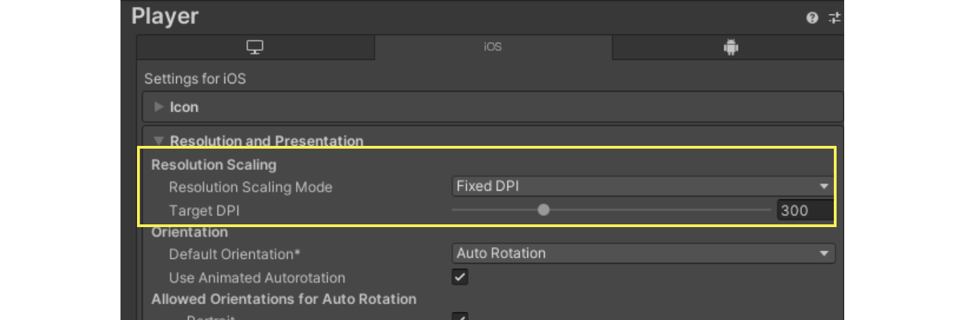
Figure 7.1: Resolution Scaling Mode
The final resolution is determined by multiplying the Target DPI value by the Resolution Scaling DPI Scale Factor value in the Quality Settings.
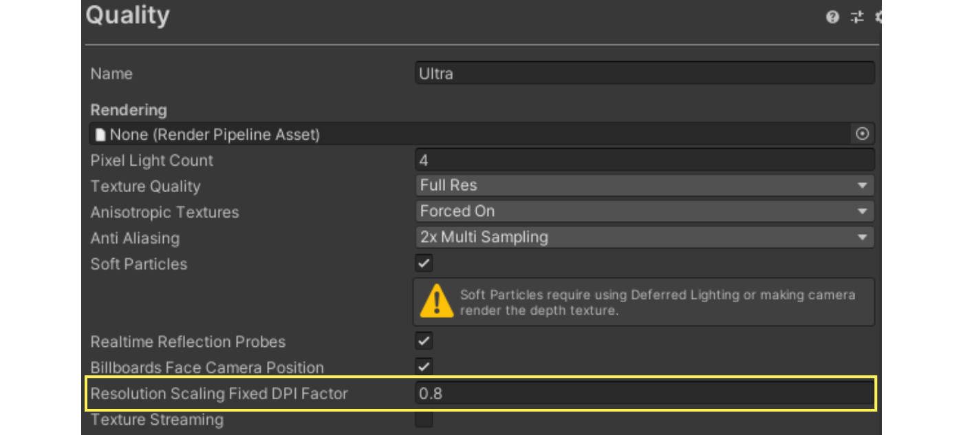
Figure 7.2: Resolution Scaling DPI Scale Factor
7.1.2. Resolution Scaling by Script
To dynamically change the drawing resolution from a script, call Screen.SetResolution.
The current resolution can be obtained at Screen.width or Screen.height, and DPI can be obtained at Screen.dpi.
List 7.1: Screen.SetResolution
public void SetupResolution() { var factor = 0.8f; // Get current resolution with Screen.width, Screen.height var width = (int)(Screen.width * factor); var height = (int)(Screen.height * factor); // Set Resolution Screen.SetResolution(width, height, true); } |
Resolution settings at Screen.SetResolution are reflected only on the actual device.
Note that changes are not reflected in the Editor.
7.2. Semi-transparency and overdraw
The use of translucent materials is controlled by the overdraw overdraw.Overdraw is the drawing of a fragment multiple times per pixel on the screen, and it affects performance in proportion to the load on the fragment shader.
Particularly when a large number of translucent particles are generated, such as in a particle system, a large amount of overdraw is often generated.
The following methods can be used to reduce the increased drawing load caused by overdraws.
- Reduce unnecessary drawing area
- Reduce as much as possible the number of areas where textures are completely transparent, as they are also subject to rendering.
- Use lightweight shaders for objects that may cause overdraw.
- Avoid using semi-transparent materials as much as possible.
- Use opaque materials to simulate the appearance of translucency Dithering is another technique to consider.
In the Editor of the Built-in Render Pipeline, set the Scene view mode to Overdraw in the Editor of the Built-in Render Pipeline, which is useful as a basis for adjusting overdraw.
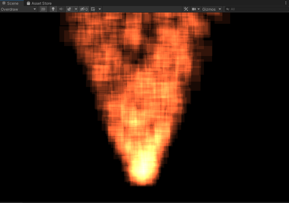
Figure 7.3: Overdraw mode
The Universal Render Pipeline supports the Scene Debug View Modes implemented in the Universal Render Pipeline since Unity 2021.2.
7.3. Reducing Draw Calls
Increasing the number of draw calls often affects the CPU load.Unity has several features to reduce the number of draw calls.
7.3.1. Dynamic batching
Dynamic batching is a feature for batching dynamic objects at runtime.This feature can be used to consolidate and reduce draw calls on dynamic objects that use the same material.
To use it, go to Player Settings and select Dynamic Batching item in the Player Settings.
Also, in the Universal Render Pipeline, you can enable Dynamic Batching item in the Universal Render Pipeline Asset.However, the use of Dynamic Batching is deprecated in the Universal Render Pipeline.
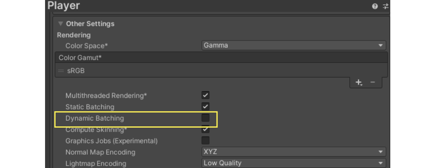
Figure 7.4: Dynamic Batching Settings
Because dynamic batching is a CPU-intensive process, many conditions must be met before it can be applied to an object.The main conditions are listed below.
- Reference to the same material
- The object is being rendered with MeshRenderer or Particle System.
- Other components such as SkinnedMeshRenderer are not subject to dynamic batching
- The number of mesh vertices is less than 300.
- No multipath is used
- Not affected by real-time shadows
Dynamic batching may not be recommended because of its impact on steady CPU load.See below. SRP Batcher described below can be used to achieve an effect similar to dynamic batching.
7.3.2. Static batching
Static batching is a function for batching objects that do not move in the scene.This feature can be used to reduce draw calls on static objects using the same material.
Similarly to dynamic batching, from the Player Settings, click on the Static Batching from the Player Settings.
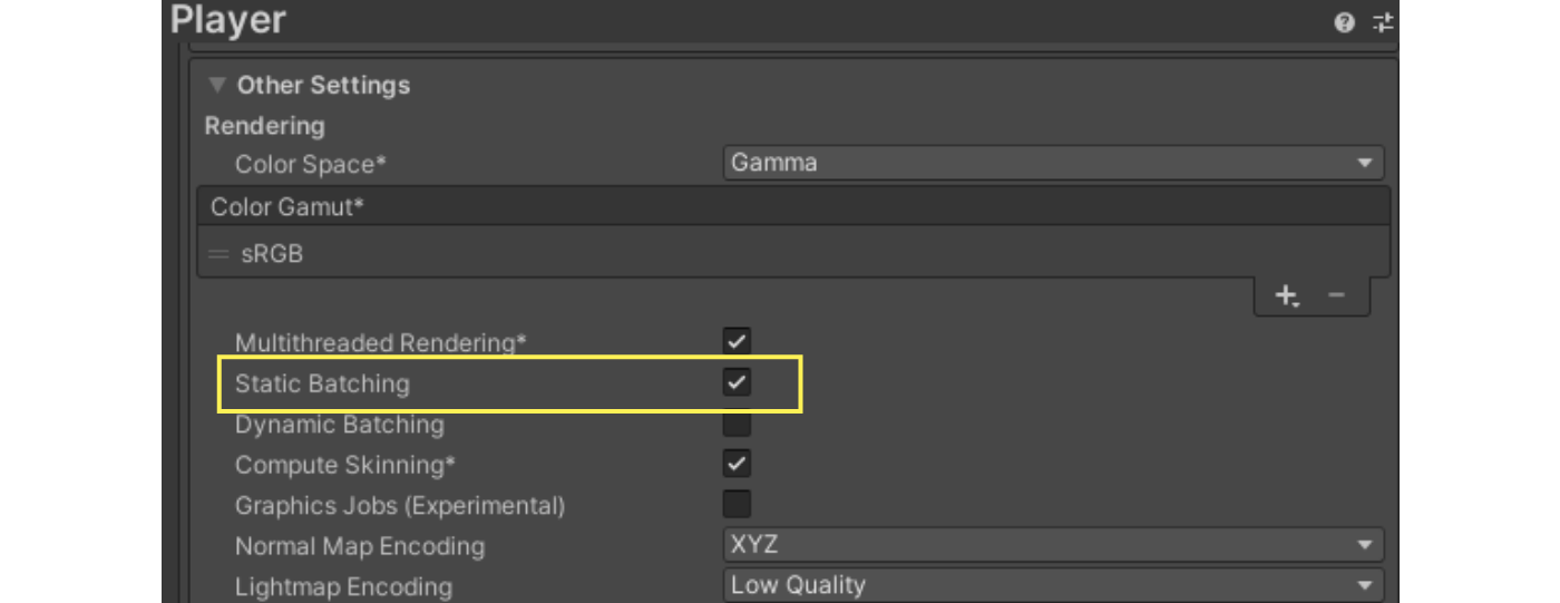
Figure 7.5: Static Batching Settings
To make an object eligible for static batching, set the object's static flag flag of the object must be enabled.Specifically, the Batching Static sub-flag in the static flag must be enabled.
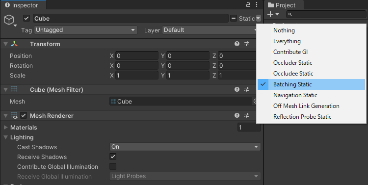
Figure 7.6: Batching Static
Static batching differs from dynamic batching in that it does not involve vertex conversion processing at runtime, so it can be performed with a lower load.However, it should be noted that it consumes a lot of memory to store the mesh information combined by batch processing.
7.3.3. GPU Instancing
GPU instancing is a function for efficiently drawing objects of the same mesh and material.It is expected to reduce draw calls when drawing the same mesh multiple times, such as grass or trees.
To use GPU instancing, go to the material's Inspector and click on Enable Instancing from the material's Inspector.
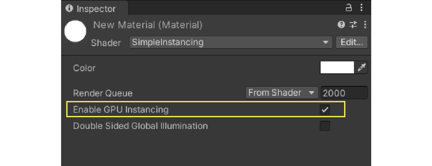
Figure 7.7: Enable Instancing
Creating shaders that can use GPU instancing requires some special handling.Below is an example shader code with a minimal implementation for using GPU instancing in a built-in render pipeline.
List 7.2: Shaders that support GPU instancing
Shader "SimpleInstancing"
{
    Properties
    {
        _Color ("Color", Color) = (1, 1, 1, 1)
    }

    CGINCLUDE

    #include "UnityCG.cginc"

    struct appdata
    {
        float4 vertex : POSITION;
        UNITY_VERTEX_INPUT_INSTANCE_ID
    };

    struct v2f
    {
        float4 vertex : SV_POSITION;
        //  Required only when accessing INSTANCED_PROP in fragment shaders
        UNITY_VERTEX_INPUT_INSTANCE_ID
     };

    UNITY_INSTANCING_BUFFER_START(Props)
        UNITY_DEFINE_INSTANCED_PROP(float4, _Color)
    UNITY_INSTANCING_BUFFER_END(Props)

    v2f vert(appdata v)
    {
        v2f o;

        UNITY_SETUP_INSTANCE_ID(v);

        //  Required only when accessing INSTANCED_PROP in fragment shaders
        UNITY_TRANSFER_INSTANCE_ID(v, o);

         o.vertex = UnityObjectToClipPos(v.vertex);
        return o;
    }

    fixed4 frag(v2f i) : SV_Target
    {
        //  Only required when accessing INSTANCED_PROP with fragment shaders
        UNITY_SETUP_INSTANCE_ID(i);

        float4 color = UNITY_ACCESS_INSTANCED_PROP(Props, _Color);
        return color;
    }

    ENDCG

    SubShader
    {
        Tags { "RenderType"="Opaque" }
        LOD 100

        Pass
        {
            CGPROGRAM
            #pragma vertex vert
            #pragma fragment frag
            #pragma multi_compile_instancing
            ENDCG
        }
    }
}
|
GPU instancing only works on objects that reference the same material, but you can set properties for each instance.You can set the target property as a property to be changed individually by enclosing it with UNITY_INSTANCING_BUFFER_START(Props) and UNITY_INSTANCING_BUFFER_END(Props), as in the shader code above.
This property can then be set in C# to MaterialPropertyBlock API in C# to set properties such as individual colors.Just be careful not to use MaterialPropertyBlock for too many instances, as accessing the MaterialPropertyBlock may affect CPU performance.
7.3.4. SRP Batcher
SRP Batcher is a Scriptable Render Pipeline (SRP) that is used in the Scriptable Render Pipeline is a feature to reduce the CPU cost of rendering that is only available in the Scriptable Render Pipeline.This feature allows multiple shader set-pass calls that use the same shader variant to be processed together.
To use the SRP Batcher, you need to add the Scriptable Render Pipeline Asset from the Inspector of the SRP Batcher from the Inspector of the Scriptable Render Pipeline Asset.
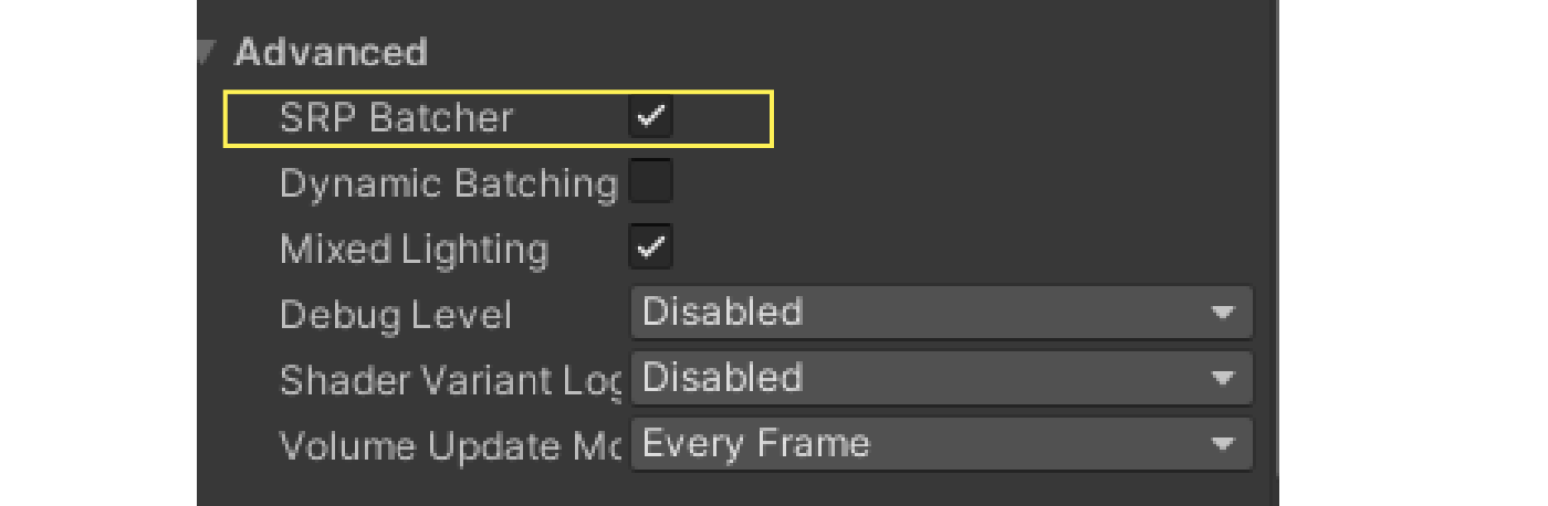
Figure 7.8: Enabling the SRP Batcher
You can also enable or disable the SRP Batcher at runtime with the following C# code
List 7.3: Enabling SRP Batcher
GraphicsSettings.useScriptableRenderPipelineBatching = true; |
The following two conditions must be met to make shaders compatible with SRP Batcher
- Define built-in properties defined per object in a single CBUFFER 2. called 1. UnityPerDraw
- Define properties per material in a single CBUFFER called UnityPerMaterial
For UnityPerDraw Universal Render Pipeline and other shaders basically support it by default, but you need to set up your own CBUFFER forUnityPerMaterial.
Surround the properties for each material with CBUFFER_START(UnityPerMaterial) and CBUFFER_END as shown below.
List 7.4: UnityPerMaterial
Properties
{
    _Color1 ("Color 1", Color) = (1,1,1,1)
    _Color2 ("Color 2", Color) = (1,1,1,1)
}

CBUFFER_START(UnityPerMaterial)

float4 _Color1;
float4 _Color2;

CBUFFER_END
|
With the above actions, you can create a shader that supports SRP Batcher, but you can also check if the shader in question supports SRP Batcher fromInspector.
In the Inspector of the shader, click on the SRP Batcher item in the shader's Inspector is compatible the shader is compatible with SRP Batcher, andIf it is "not compatible is not compatible, it means it is not supported.
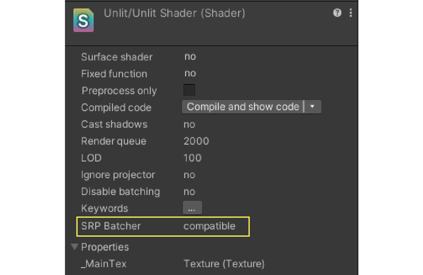
Figure 7.9: Shaders that are compatible with SRP Batcher
7.4. SpriteAtlas
2D games and UIs often use many sprites to build the screen.In such cases, a function to avoid generating a large number of draw calls is SpriteAtlas to avoid a large number of draw calls in such cases.
SpriteAtlas reduces draw calls by combining multiple sprites into a single texture.
To create a SpriteAtlas, first go to the Package Manager and click on 2D Sprite must first be installed in the project from the Package Manager.
Figure 7.10: 2D Sprite
After installation, right click in the Project view and select "Create -> 2D -> Sprite Atlas" to create the SpriteAtlas asset.
Figure 7.11: Creating SpriteAtlas
To specify the sprites that will be made into an atlas, go to the SpriteAtlas inspector and select Objects for Packing item of the SpriteAtlas inspector to specify the sprite or the folder that contains the sprite.
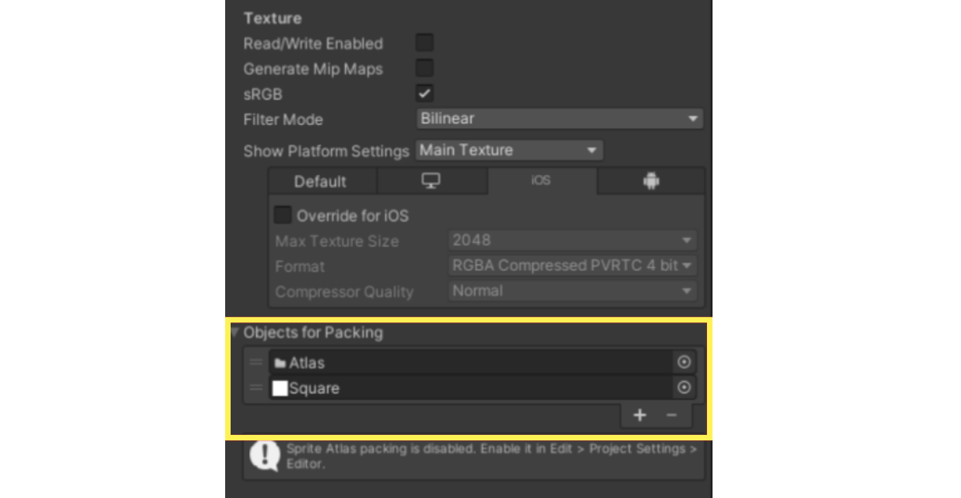
Figure 7.12: Setting up Objects for Packing
With the above settings, the sprite will be atlased during build and playback in the Unity Editor, and the integrated SpriteAtlas texture will be referenced when drawing the target sprite.
Sprites can also be obtained directly from SpriteAtlas with the following code.
List 7.5: Loading a Sprite from SpriteAtlas
[SerializeField] private SpriteAtlas atlas; public Sprite LoadSprite(string spriteName) { // Obtain a Sprite from SpriteAtlas with the Sprite name as an argument var sprite = atlas.GetSprite(spriteName); return sprite; } |
Loading a single Sprite in the SpriteAtlas consumes more memory than loading just one, since the texture of the entire atlas is loaded.Therefore, the SpriteAtlas should be used with care and divided appropriately.
This section is written targeting SpriteAtlas V1.SpriteAtlas V2 may have significant changes in operation, such as not being able to specify the folder of the sprite to be atlased.
7.5. Culling
In Unity, to omit in advance the processing of the parts that will not be displayed on the screen in the final version. culling process is used to eliminate the part of the image that will not ultimately be displayed on the screen in advance.
7.5.1. Visual Culling
Visual Culling is a process that omits objects outside of the camera's rendering area, the viewing cone, from the rendering.This prevents objects outside the camera's range from being calculated for rendering.
Visual cone culling is performed by default without any settings.For vertex shader-intensive objects, culling can be applied by dividing the mesh appropriately to reduce the cost of rendering.
7.5.2. Rear Culling
Rear culling is the process of omitting from rendering the backside of polygons that are (supposed to be) invisible to the camera.Most meshes are closed (only the front polygons are visible to the camera), so the backs of polygons do not need to be drawn.
In Unity, if you do not specify this in the shader, the back side of the polygon is subject to culling, but you can switch the culling setting by specifying it in the shader.The following is described in the SubShader.
List 7.6: Culling setting
SubShader
{
    Tags { "RenderType"="Opaque" }
    LOD 100

    Cull Back //  Front, Off

    Pass
    {
        CGPROGRAM
        #pragma vertex vert
        #pragma fragment frag
        ENDCG
    }
}
|
There are three settings: Back, Front, and Off. The effect of each setting is as follows.
- Back - Do not draw polygons on the side opposite to the viewer's point of view
- Front - Do not draw polygons in the same direction as the viewpoint
- Off - Disable back culling and draw all faces.
7.5.3. Occlusion culling
Occlusion culling is the process of omitting objects from the rendering that are not visible to the camera because they are occluded by objects.This function uses pre-baked occlusion data to determine if an object is occluded at run-time and removes the occluded object from the rendering.
To make an object eligible for occlusion culling, set the inspector's static flag to Occluder Static or Occludee Static from the inspector static flag.If Occluder Static is disabled and Occludee Static is enabled, the object will no longer be considered as the occluder, but only as the occluded object.In the opposite case, the object is no longer considered as a cloaked object and is processed as a cloaked object only.
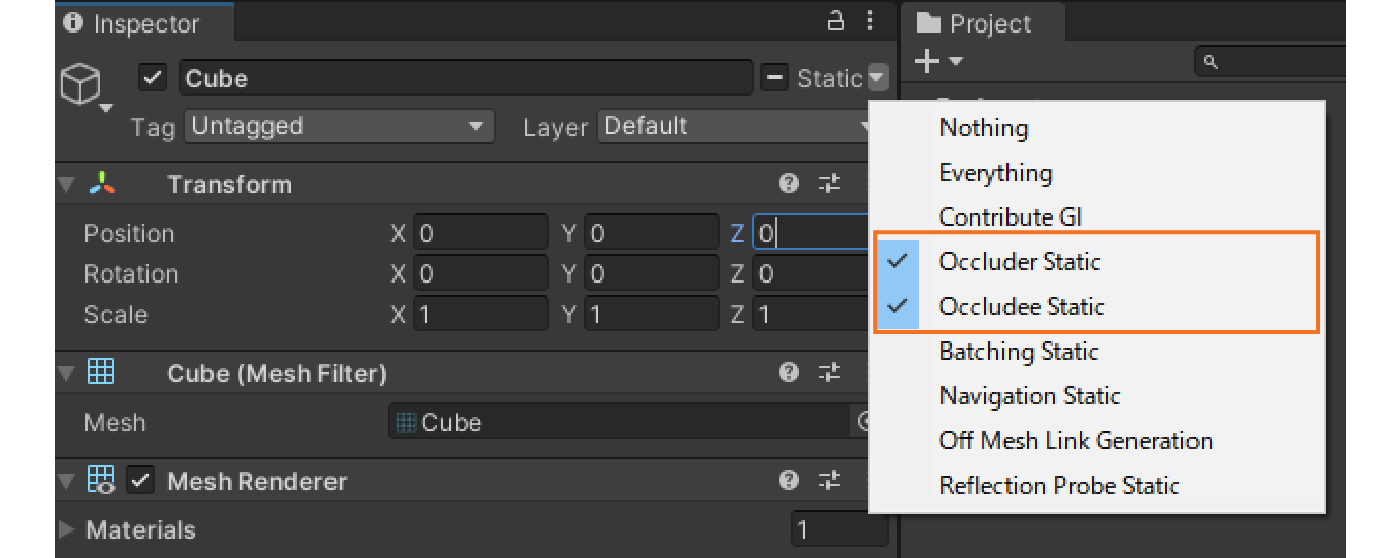
Figure 7.13: static flag for occlusion culling
To pre-bake for occlusion culling, the Occlusion Culling window is displayed to pre-bake for occlusion culling.In this window, you can change the static flags for each object, change the bake settings, etc., and press the Bake button Bake can be performed by pressing the Bake button.
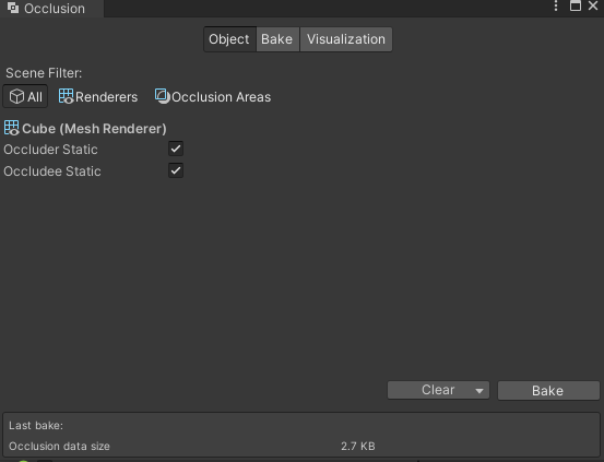
Figure 7.14: Occlusion Culling Window
Occlusion culling reduces rendering cost, but at the same time, it puts more load on the CPU for the culling process, so it is necessary to balance each load and make appropriate settings.
Only the object rendering process is reduced by occlusion culling, while processes such as real-time shadow rendering remain unchanged.
7.6. Shaders
Shaders are very effective for graphics, but they often cause performance problems.
7.6.1. Reducing the precision of floating-point types
GPUs (especially on mobile platforms) compute faster with smaller data types than with larger ones.Therefore, floating-point types should be replaced with float type (32bit) to half type (16bit) is effective when it is possible to replace the floating-point type.
The float type should be used when precision is required, such as in depth calculations, but in color calculations, even if the precision is reduced, it is difficult to cause a large difference in the resulting appearance.
7.6.2. Performing Calculations with Vertex Shaders
The vertex shader is executed for the number of vertices in the mesh, and the fragment shader is executed for the number of pixels that will eventually be written.In general, vertex shaders are often executed less frequently than fragment shaders, so it is best to perform complex calculations in the vertex shader whenever possible.
The vertex shader calculation results are passed to the fragment shader via shader semantics, but it should be noted that the values passed are interpolated and may look different than if they were calculated in the fragment shader.
List 7.7: Precomputation with vertex shaders
CGPROGRAM
#pragma vertex vert
#pragma fragment frag

#include "UnityCG.cginc"

struct appdata
{
    float4 vertex : POSITION;
    float2 uv : TEXCOORD0;
};

struct v2f
{
    float2 uv : TEXCOORD0;
    float3 factor : TEXCOORD1;
    float4 vertex : SV_POSITION;
};

sampler2D _MainTex;
float4 _MainTex_ST;

v2f vert (appdata v)
{
    v2f o;
    o.vertex = UnityObjectToClipPos(v.vertex);
    o.uv = TRANSFORM_TEX(v.uv, _MainTex);

    //  Complex precomputations.
    o.factor = CalculateFactor();

    return o;
}

fixed4 frag (v2f i) : SV_Target
{
    fixed4 col = tex2D(_MainTex, i.uv);

    //  Values computed in the vertex shader are used in the fragment shader
    col *= i.factor;

    return col;
}
ENDCG
|
7.6.3. Prebuild information into textures
If the results of complex calculations in the shader are not affected by external values, then storing the pre-calculated results as elements in the texture is an effective way to do so.
This can be done by implementing a dedicated texture generation tool in Unity or as an extension to various DCC tools.If the alpha channel of a texture already in use is not being used, it is a good idea to write to it or prepare a dedicated texture.
For example, the LUT (color correspondence table) used for color grading, for example, will pre-correct the texture so that the coordinates of each pixel correspond to each color.By sampling the texture in the shader based on the original color, the result is almost the same as if the pre-correction had been applied to the original color.

Figure 7.15: LUT texture (1024x32) before color correction
7.6.4. ShaderVariantCollection
ShaderVariantCollection can be used to compile shaders before they are used to prevent spikes.
ShaderVariantColletion allows you to keep a list of shader variants used in your game as assets.It is created by selecting "Create -> Shader -> Shader Variant Collection" from the Project view.
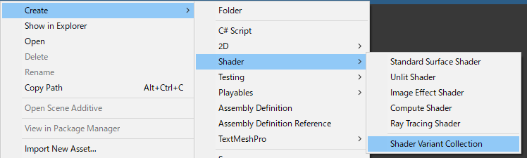
Figure 7.16: Creating a ShaderVariantCollection
From the Inspector view of the created ShaderVariantCollection, press Add Shader to add the target shader, and then select which variants to add for the shader.
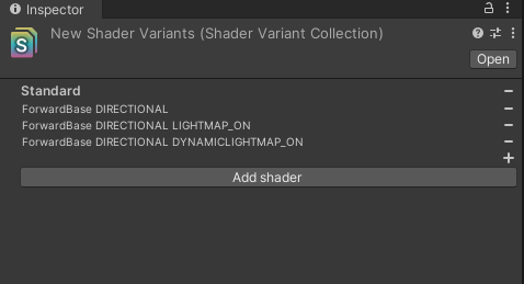
Figure 7.17: ShaderVariantCollection Inspector
ShaderVariantCollection is added to the Graphics Settings Shader preloading in the Graphics Settings. Preloaded Shaders in the Shader preloading section of the Graphics Settings,to set the shader variants to be compiled at application startup.
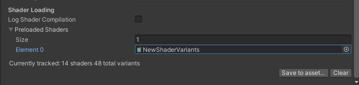
Figure 7.18: Preloaded Shaders
You can also set the shader variants from a script by calling ShaderVariantCollection.WarmUp() from a script to explicitly precompile the shader variants contained in the corresponding ShaderVariantCollection.
List 7.8: ShaderVariantCollection.
public void PreloadShaderVariants(ShaderVariantCollection collection)
{
    //  Explicitly precompile shader variants
    if (!collection.isWarmedUp)
    {
        collection.WarmUp();
    }
}
|
7.7. Lighting
Lighting is one of the most important aspects of a game's artistic expression, but it often has a significant impact on performance.
7.7.1. Real-time shadows
Generating real-time shadows consumes a large amount of draw call and fill rate.Therefore, careful consideration should be given to settings when using real-time shadows.
Draw Call Reduction
The following policies can be used to reduce draw calls for shadow generation.
- Reduce the number of objects that drop shadows
- Consolidate draw calls by batching
There are several ways to reduce the number of objects dropping shadows, but a simple method is to use the MeshRenderer's Cast Shadows setting in MeshRenderer to off.This will remove the object from the shadow draw call.This setting is usually turned on in Unity and should be noted in projects that use shadows.
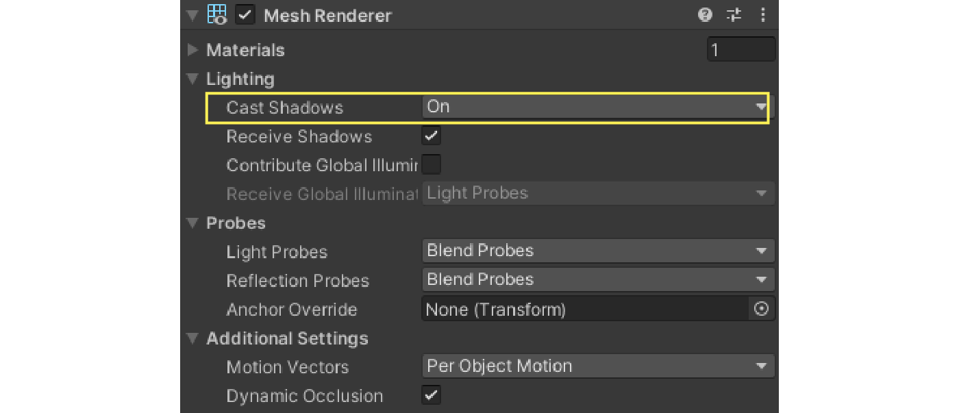
Figure 7.19: Cast Shadows
It is also useful to reduce the maximum distance an object can be drawn in the shadow map.In the Quality Settings Shadow Distance in the Quality Settings to reduce the number of objects that cast shadows to the minimum necessary.Adjusting this setting will also reduce the resolution of the shadows, since shadows will be drawn at the minimum range for the resolution of the shadow map.
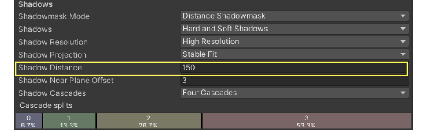
Figure 7.20: Shadow Distance
As with normal rendering, shadow rendering can be subject to batching to reduce draw calls.See "7.3 Reducing Draw Calls" for more information on batching techniques.
Fill Rate Savings
The fill rate of a shadow depends on both the rendering of the shadow map and the rendering of the object affected by the shadow.
The respective fill rates can be saved by adjusting several settings in the Shadows section of the Quality Settings.
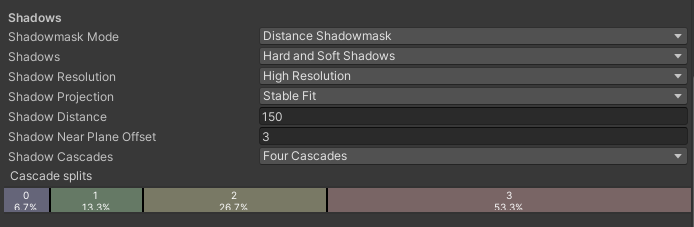
Figure 7.21: Quality Settings -> Shadows
The Shadows section allows you to change the format of the shadows, and the Hard Shadows will produce a clear shadow border, but with a relatively low load, while Soft Shadows is more expensive, but it can produce blurred shadow borders.
Shadow Resolution and Shadow Cascades items affect the resolution of the shadow map, with larger settings increasing the resolution of the shadow map and consuming more fill rate.However, since these settings have a great deal to do with the quality of the shadows, they should be carefully adjusted to strike a balance between performance and quality.
Some settings can be adjusted using the Light component's Inspector, so it is possible to change the settings for individual lights.
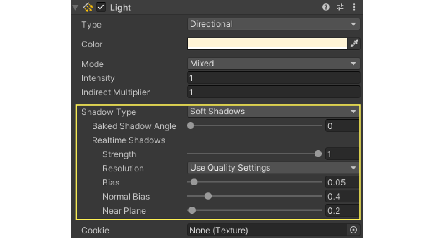
Figure 7.22: Shadow settings for the Light component
Pseudo Shadow
Depending on the game genre or art style, it may be effective to use plate polygons or other materials to simulate the shadows of objects.Although this method has strong usage restrictions and is not highly flexible, it is far lighter than the usual real-time shadow rendering method.
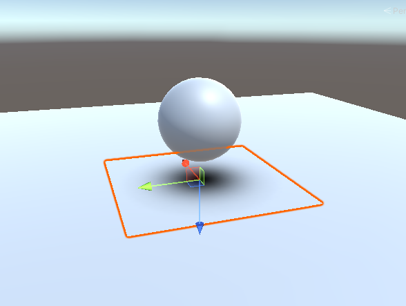
Figure 7.23: Pseudo-shadow using plate polygons
7.7.2. Light Mapping
By baking lighting effects and shadows into textures in advance, quality lighting expressions can be achieved with considerably lower load than real-time generation.
To bake a lightmap, first add a Light component placed in the scene Mode item of the Light component placed in the scene to Mixed or Baked Mixed or Baked.
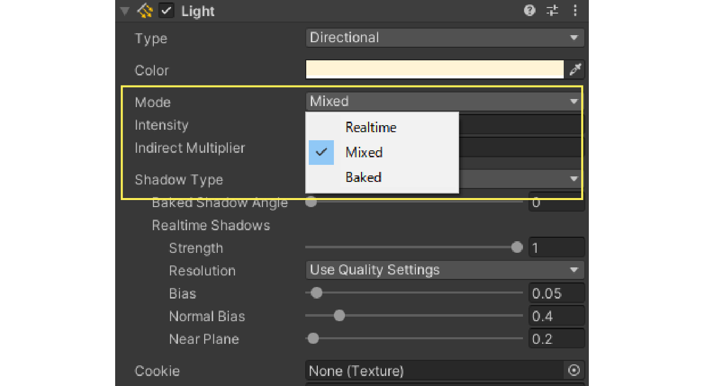
Figure 7.24: Mode setting for Light
Also, activate the static flag of the object to be baked.
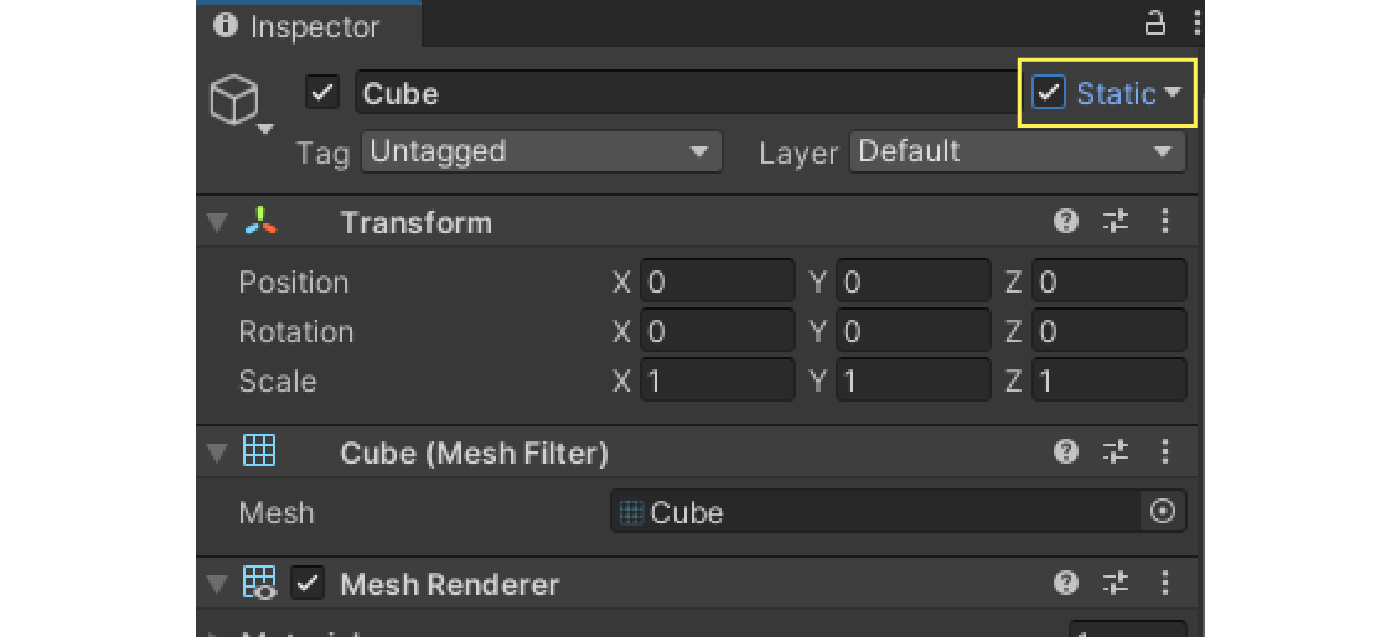
Figure 7.25: Enable static
In this state, select "Window -> Rendering -> Lighting" from the menu to display the Lighting view.
The default setting is Lighting Settings asset is not specified, we need to change the settings by clicking on New Lighting Settings button to create a new one.
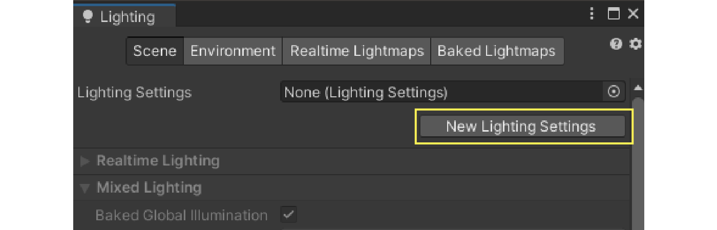
Figure 7.26: New Lighting Settings
The main settings for lightmaps are Lightmapping Settings tab.
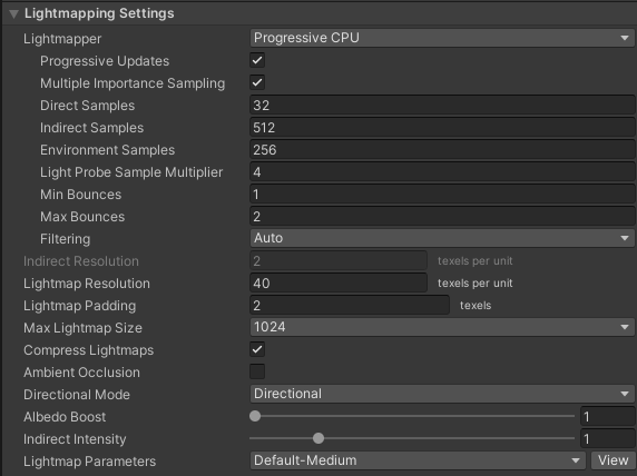
Figure 7.27: Lightmapping Settings
There are many settings that can be adjusted to change the speed and quality of lightmap baking.Therefore, these settings should be adjusted appropriately for the desired speed and quality.
Of these settings, the one that has the greatest impact on performance is Lightmap Resolution This setting has the largest impact on performance.This setting determines how many lightmap texels are allocated per unit in Unity, and since the final lightmap size varies depending on this value, it has a significant impact on storage and memory capacity, texture access speed, and other factors.
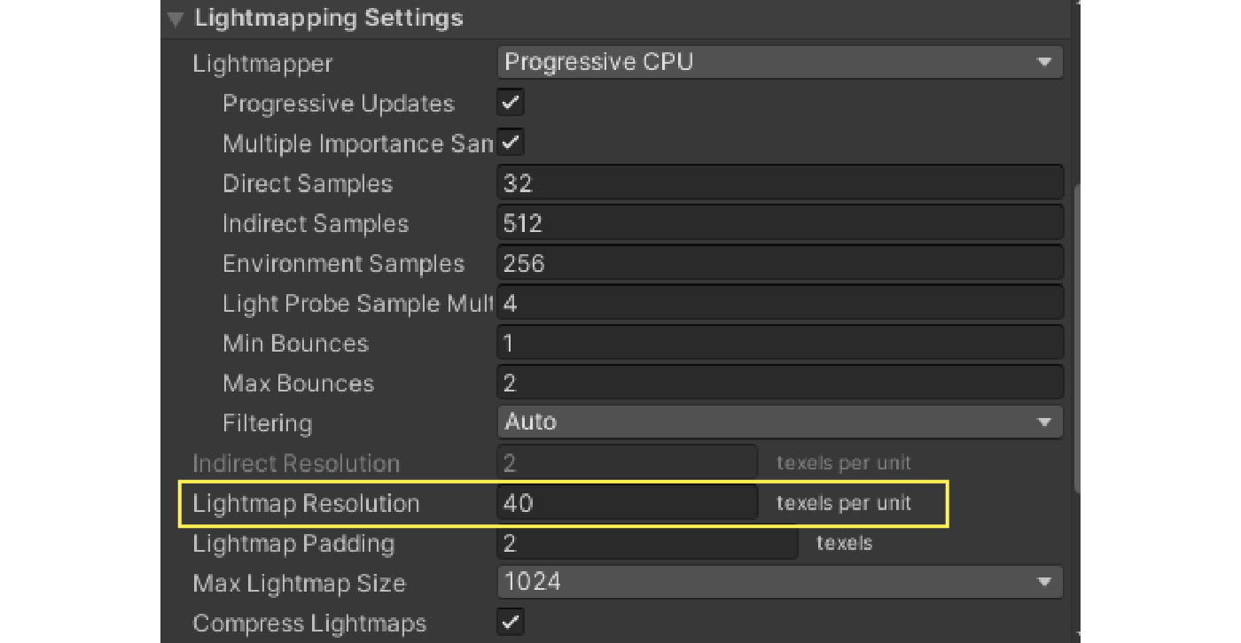
Figure 7.28: Lightmap Resolution
Finally, at the bottom of the Inspector view, the Generate Lighting button at the bottom of the Inspector view to bake the lightmap.Once baking is complete, you will see the baked lightmap stored in a folder with the same name as the scene.
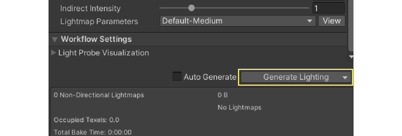
Figure 7.29: Generate Lighting
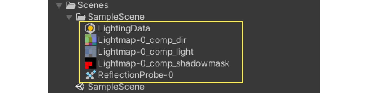
Figure 7.30: Baked lightmap
7.8. Level of Detail
It is inefficient to render objects that are far away from the camera in high-polygon, high-definition.Level of Detail (LOD) method can be used to reduce the level of detail of an object depending on its distance from the camera.
In Unity, objects are assigned to a LOD Group component to the object.
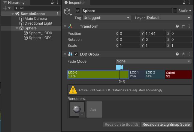
Figure 7.31: LOD Group
By placing a renderer with a mesh of each LOD level on a child of a GameObject to which a LOD Group is attached and setting each LOD level in the LOD Group, the LOD level can be switched according to the camera.It is also possible to set which LOD level is assigned to each LOD Group in relation to the camera's distance.
Using LOD generally reduces the drawing load, but one should be aware of memory and storage pressures since all meshes for each LOD level are loaded.
7.9. Texture Streaming
Unity's Texture Streaming can be used to reduce the memory footprint and load time required for textures.Texture streaming is a feature that saves GPU memory by loading mipmaps based on the camera position in the scene.
To enable this feature, go to the Quality Settings Texture Streaming in the Quality Settings.
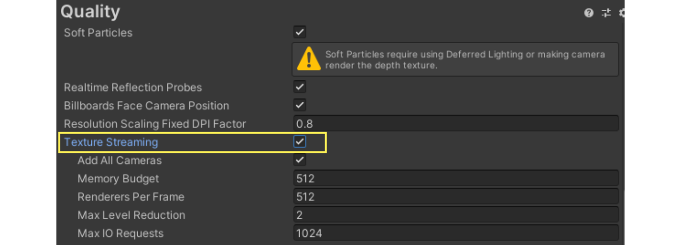
Figure 7.32: Texture Streaming
In addition, the texture import settings must be changed to allow streaming of texture mipmaps.Open the texture inspector and select Advanced Streaming Mipmaps Streaming Mipmaps in the Advanced settings.
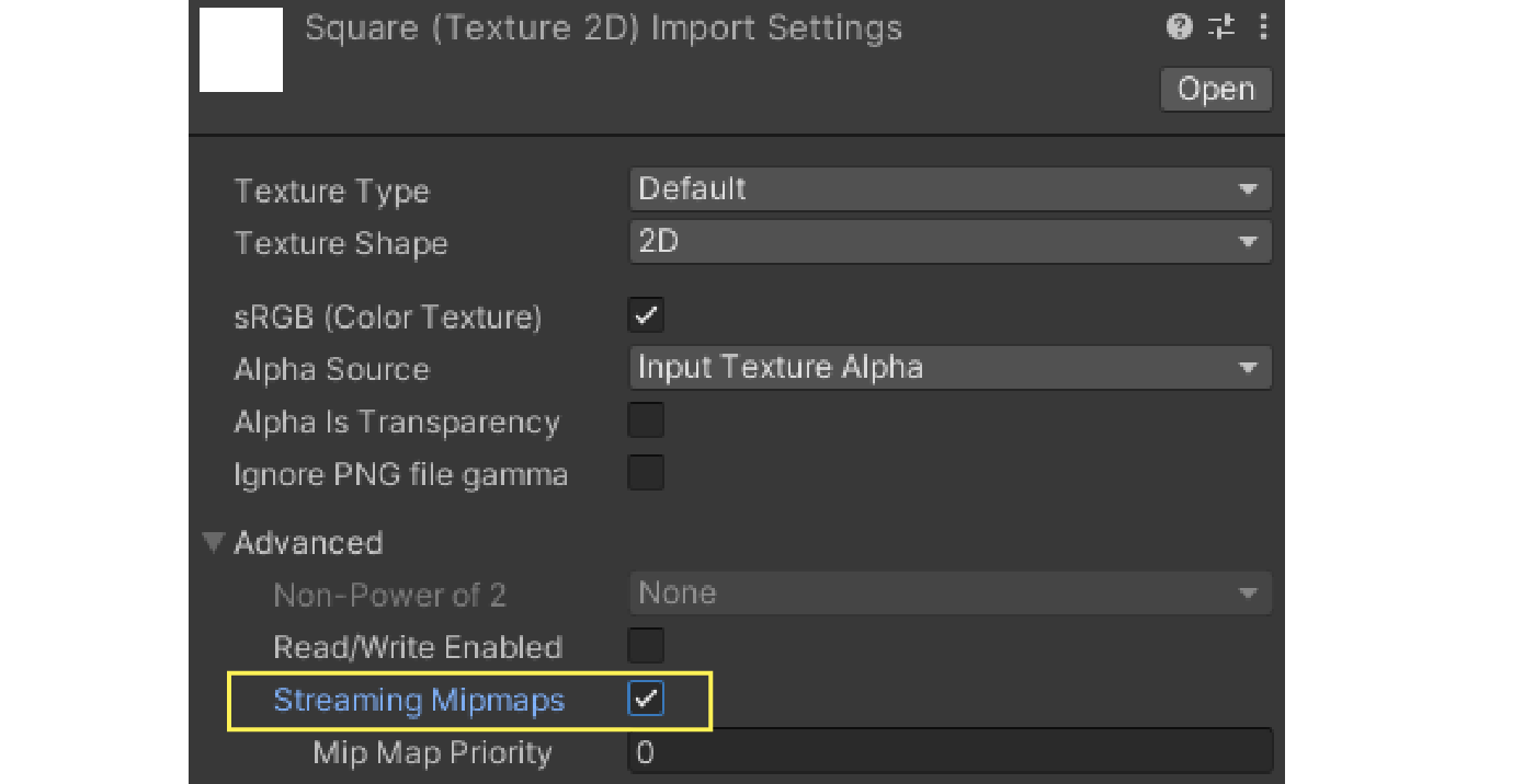
Figure 7.33: Streaming Mipmaps
These settings enable streaming mipmaps for the specified texture.Also, in the Quality Settings Memory Budget under Quality Settings to limit the total memory usage of the loaded textures.The texture streaming system will load the mipmaps without exceeding the amount of memory set here.