Chapter 1. Unity 6 Render Graph Tile Memory Optimization
1.0.1. Introduction
This chapter explains how to use Unity 6's Render Graph to take advantage of the tile memory of mobile GPUs (tile-based rendering architecture) and reduce GPU time, memory bandwidth, and memory usage. In mobile game development, memory bandwidth often becomes the bottleneck before GPU compute performance does. Memory bandwidth consumption is also directly tied to power consumption and heat, so it affects device temperature and battery drain as well as frame rate. This chapter covers the following four themes. Each has a section of the same name.
- Tile memory load/store
- Render Pass/Subpass
- Frame buffer fetch
- Memoryless
1.1. Fundamentals of Tile-Based Rendering
This section explains why mobile GPUs have tile memory.
1.1.1. Mobile GPUs and Memory Bandwidth
On modern GPUs, the gap between compute speed and memory read/write speed keeps widening, and memory access has become a major bottleneck. GPU core compute performance (FLOPS) grows substantially with each generation, but memory bandwidth growth has not kept pace. Discrete GPUs on PCs mitigate this problem by providing dedicated high-bandwidth graphics memory such as GDDR. Mobile SoCs cannot do the same.
| Item | PC (discrete GPU) | Mobile SoC |
|---|---|---|
| Graphics memory | Dedicated (GDDR6, etc., hundreds of GB/s) | None (LPDDR shared by CPU/GPU/ISP, etc.) |
| Bandwidth scale | Hundreds of GB/s to 1 TB/s | Tens of GB/s (and shared) |
| Power constraints | Hundreds of watts of power and cooling | A few watts, passive cooling only |
Mobile GPUs have no dedicated graphics memory and share the same LPDDR memory as the CPU. The memory is shared not only with the CPU but also with every other block on the SoC, such as the camera ISP and machine learning accelerators. The bandwidth itself is narrow, and the blocks compete for it. Furthermore, access to main memory (DRAM) is one of the most power-hungry operations on the SoC. The more bandwidth is used, the more power is consumed and the more heat is generated, thermal throttling lowers the CPU/GPU clocks, and the frame rate drops. In other words, on mobile the following chain occurs:
Memory bandwidth consumption → increased power consumption → heat → throttling → performance degradation
If a game runs at 60 FPS for the first few minutes but the frame rate drops after playing for a while, this bandwidth and heat issue is often the cause. GPUs with the tile-based rendering (TBR) architecture were created to render within this constraint.
1.1.2. IMR and TBR
To understand TBR, let us first compare it with immediate mode rendering (IMR), the architecture that is mainstream in PC GPUs. IMR rasterizes the primitives submitted by a draw call immediately, runs the fragment shader, and writes the result to the render target in memory. Reads and writes to the render target occur for every depth test and blend, but PC GPUs absorb this with high-bandwidth graphics memory and large caches. TBR, on the other hand, divides the screen into small tiles and completes rendering one tile at a time. Each shader core has a small on-chip memory called tile memory, and all drawing within a tile (reading and writing color, depth, and stencil, and blending) is performed in this tile memory. As a rule, main memory is accessed only twice: once when drawing of the tile starts (load) and once when it ends (store).
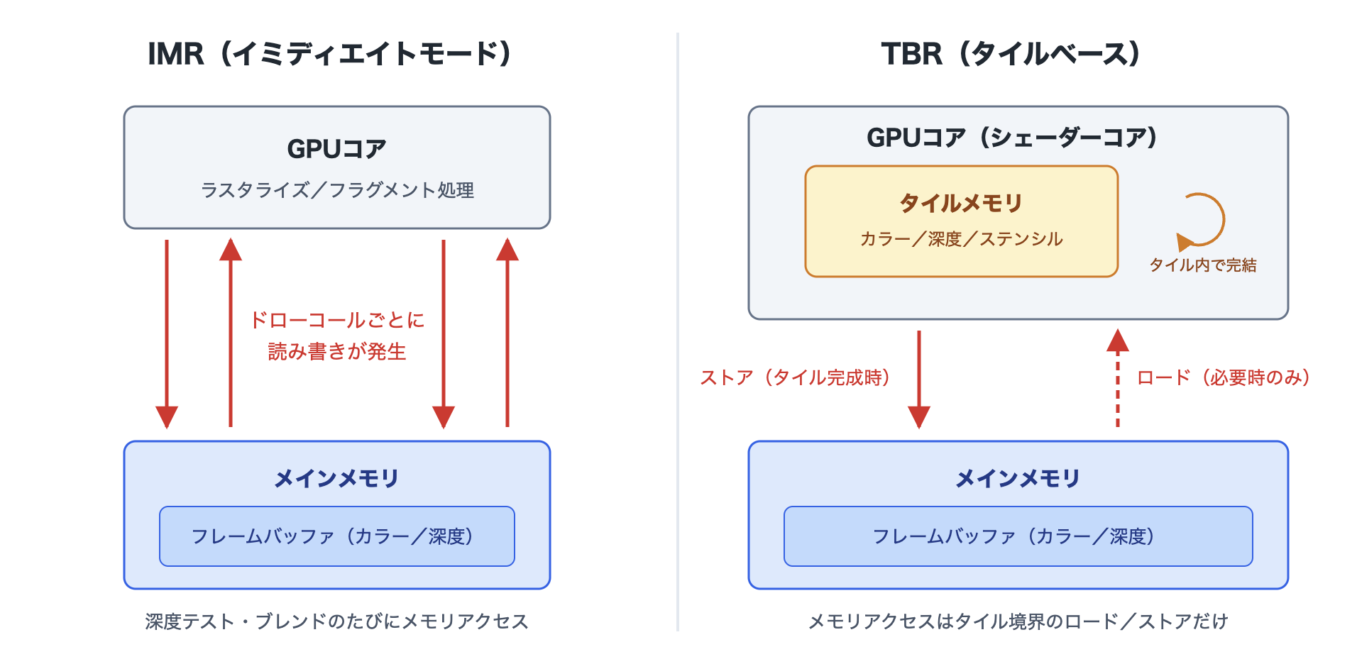
Figure 1.1: Comparison of IMR and TBR
The following figure is a conceptual diagram of a shader core in a TBR GPU. Tile memory is directly connected to the shader core. Because it is on-chip and physically close, access to tile memory is orders of magnitude faster and uses far less power than access to main memory. This structure can also be seen in real GPUs. For example, the shader core design diagram in the official ARM Mali-G71 documentation shows tile memory directly connected to the shader core.
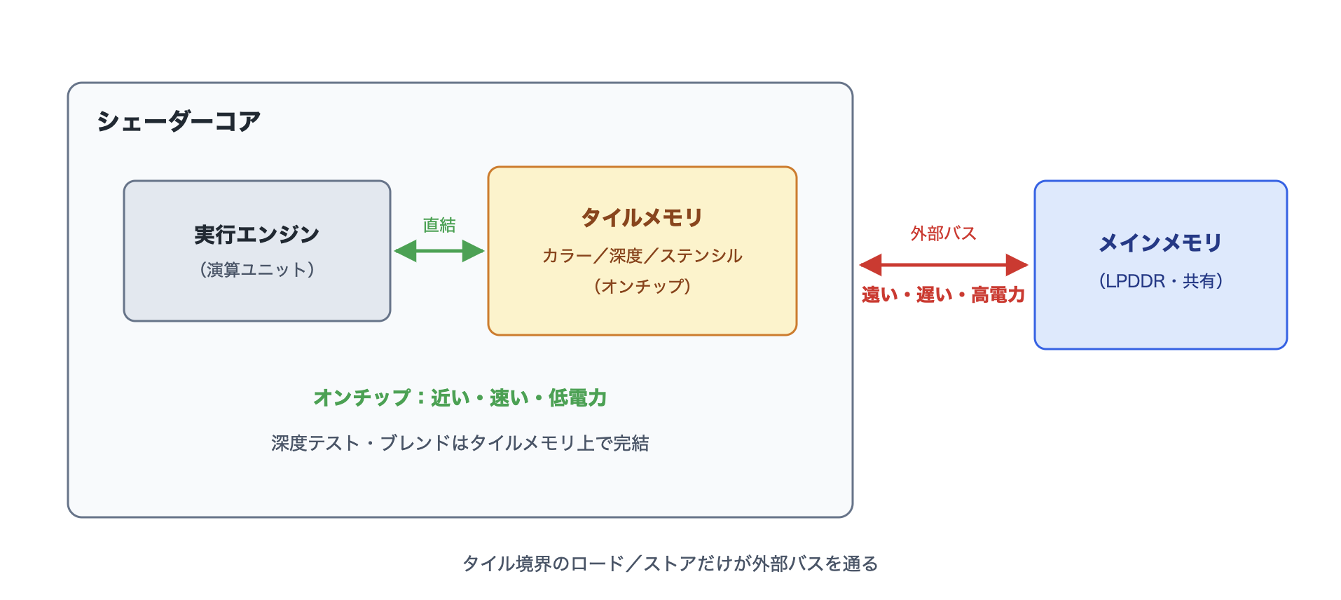
Figure 1.2: Shader core and tile memory (conceptual diagram)
In this way, depth testing and blending, which involve the heaviest memory access in IMR, are completed within tile memory in TBR.
1.1.3. The Two Phases of TBR
A TBR GPU executes the rendering of one frame in two major phases.
Binning Phase (Geometry Phase)
First, the GPU runs the vertex shaders (the position calculation part) for all draw calls in the frame and sorts which tiles each primitive overlaps (binning). The result is written to main memory as a "per-tile primitive list." Note that the binning phase itself also consumes main memory bandwidth. The more vertex data there is, the more reads and writes of the primitive list occur. This is why high-polygon scenes tend to be disadvantageous on TBR GPUs.
Rasterization Phase (Rendering Phase)
Next, the tiles are processed one at a time. For each tile, drawing proceeds as follows:
- If necessary, load the existing contents of the render target into tile memory
- Rasterize the primitives that overlap the tile and run the fragment shader (all reads and writes occur in tile memory)
- Store the completed tile contents to main memory
Steps 1 and 3 are the load/store that is the theme of this chapter. The next section, "Tile Memory Load/Store," covers them in detail, but the cost structure of TBR is that the exchange with main memory at tile boundaries is more expensive than the drawing of the tile itself.
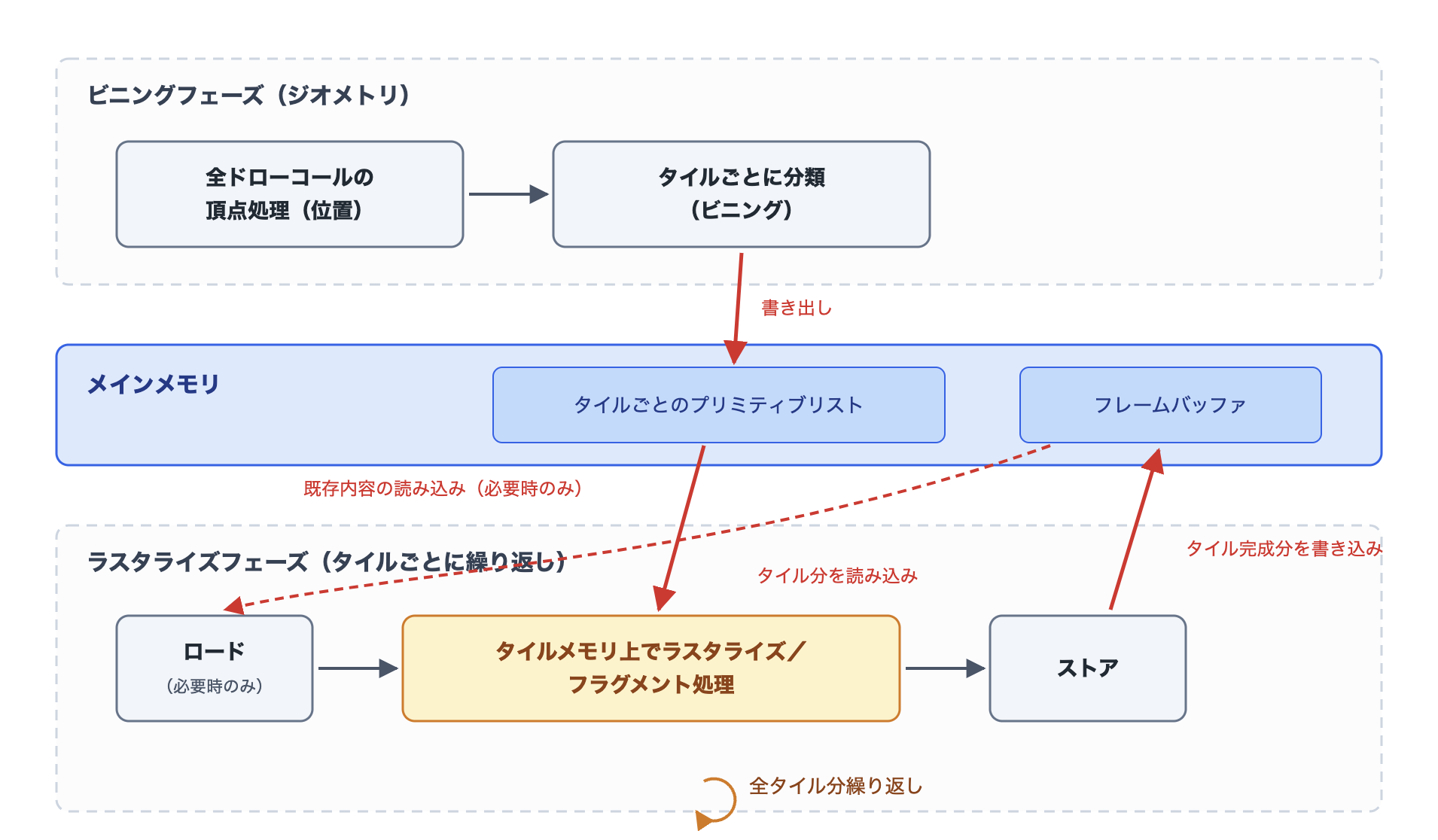
Figure 1.3: Binning phase and rasterization phase
Vendor-Specific Terminology and Characteristics
The basic structure of TBR is common, but terminology and implementation details differ by GPU vendor. In the rest of this chapter, the terms tile memory and binning are used as generic names.
| Vendor (GPU) | Phase/mechanism name | Notes |
|---|---|---|
| Qualcomm Adreno | Binning / GMEM | Uses on-chip memory called GMEM, divided as needed. Has a mode that switches to IMR-like behavior depending on the rendering content |
| ARM Mali | Tiler / Tile Memory | Tiles are basically 16×16 pixels |
| Imagination (PowerVR/IMG) | TBDR | A TBDR that performs hidden surface removal (HSR) in hardware. The IMG DXT in Pixel 10 follows this lineage |
| Apple GPU | Tile Memory | A TBDR in the PowerVR lineage. Tile memory can be handled explicitly from Metal |
1.1.4. The Four Themes of This Chapter
We have seen that load/store at tile boundaries is the cost. So how can that cost be reduced? The four themes of this chapter are all means of answering this question.
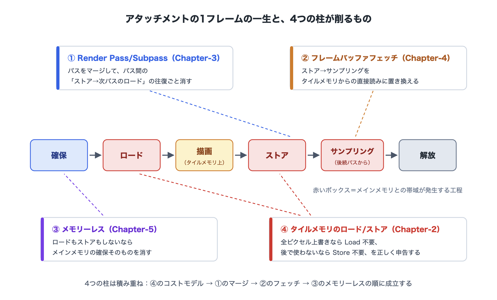
Figure 1.4: The lifetime of an attachment and the four themes
Consider the one-frame lifecycle of a render target (attachment).
Allocate → load → draw → store → sample (as a texture in subsequent passes) → release
Depending on which part of this lifecycle is reduced, the four themes can be organized as follows.
| Theme | What is reduced | Approach | Section |
|---|---|---|---|
| Load/store | Unnecessary loads and unnecessary stores | State explicitly that "no load is needed if every pixel is overwritten" and "no store is needed if the result is not used later" | "Tile Memory Load/Store" |
| Render Pass/Subpass | Store→load round trips between passes | Merge multiple passes into one Render Pass and keep intermediate results in tile memory | "Render Pass / Subpass" |
| Frame buffer fetch | Store→sample round trips | Read the result of the previous subpass directly from tile memory | "Frame Buffer Fetch" |
| Memoryless | The main memory allocation itself | If there is neither load nor store, no entity in main memory is needed | "Memoryless" |
These four are not independent techniques. Frame buffer fetch can be used only after passes are merged, and memoryless is possible only after both load and store are gone. The section structure of this chapter follows this dependency: cost model (load/store) → mechanism (subpass) → application (fetch) → finishing touch (memoryless). Render Graph is also a system that collects per-pass resource usage information (what is read and what is written) and then builds an execution plan for rendering. It can therefore automatically perform optimizations such as pass merging, load/store action determination, and making resources memoryless. What this chapter explains is, in effect, how to tell Render Graph correctly how resources are used so that these optimizations take effect.
1.1.5. How to Use the Verification Tools
In this chapter, we repeatedly check the state of the pipeline with tools before measuring. The following three are mainly used.
1.1.6. Frame Debugger
Unity's Frame Debugger (Window > Analysis > Frame Debugger) is the basic tool for checking the structure of passes. What we look at in particular in this chapter is the (RP n:m) notation in event names. If the same Render Pass number (n) is followed by consecutive subpass numbers (m), as in RP 4:0 and RP 4:1, those passes have been merged into a single Native Render Pass. Note that pass merging (Native Render Pass) works in environments such as Vulkan/Metal. If the Editor's graphics API is D3D or similar, merging cannot be observed. When checking in the Editor, change the Graphics API to Vulkan, or attach the Frame Debugger to a device build.
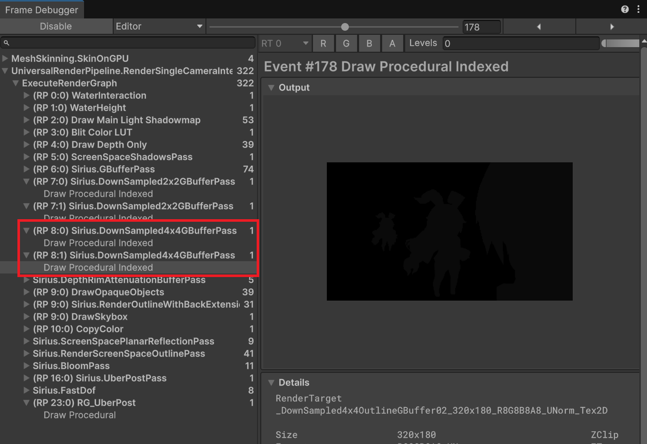
Figure 1.5: Merge state in the Frame Debugger
1.1.7. Render Graph Viewer
Render Graph Viewer (Window > Analysis > Render Graph Viewer) is a tool that visualizes the execution plan built by Render Graph itself.
- The list of passes and a timeline of the resources each pass accesses (which resource is created when and destroyed when)
- The Load Action / Store Action of each attachment and the Memoryless status. In this chapter, we use this display to check the results of optimization
- Whether passes are merged
- Why passes were not merged (Pass Break Reasoning)
The fourth item, Pass Break Reasoning, is the first information to check when passes that should be merged are not merged. It is used repeatedly from the "Render Pass / Subpass" section onward.
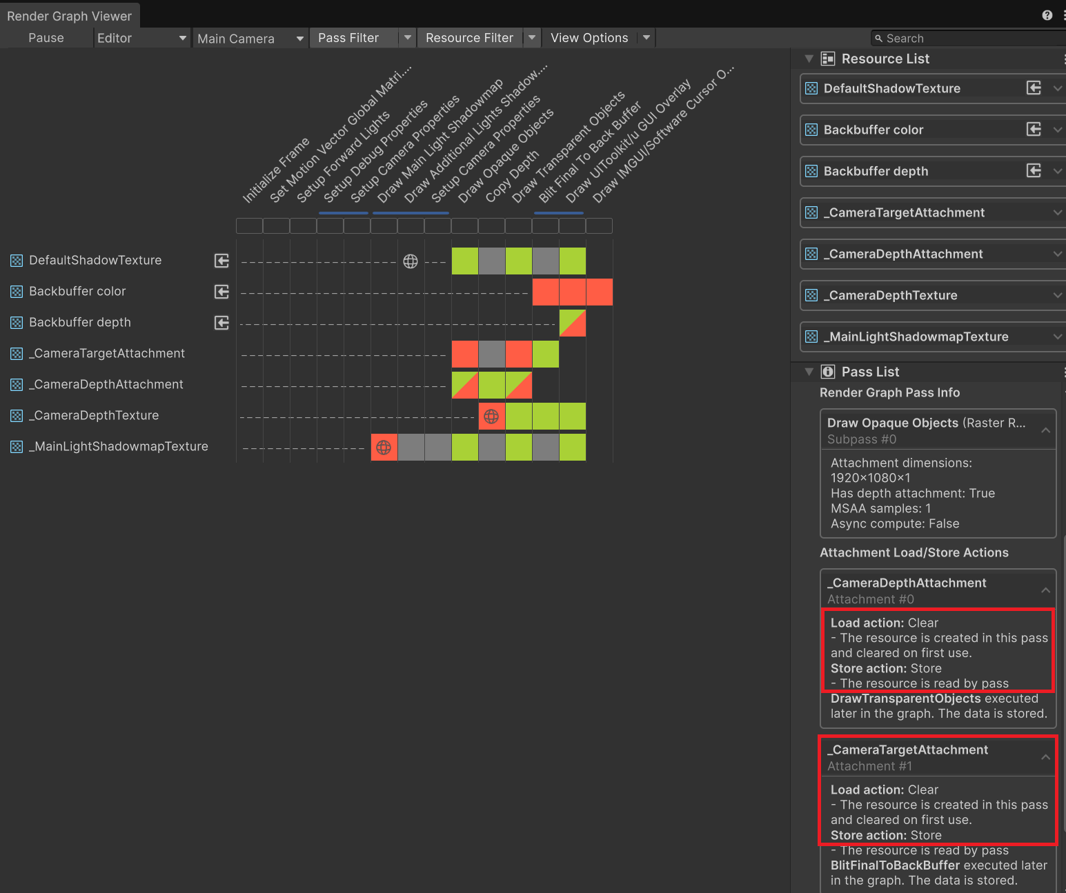
Figure 1.6: Checking merge state and load/store actions in Render Graph Viewer
1.1.8. RenderDoc
When you capture Vulkan with RenderDoc, you can check the loadOp/storeOp specified for each Render Pass attachment at the API level. Use it when you want to dig one level deeper than the Render Graph Viewer display, or when you want to compare Unity's display with the values actually passed to the driver.
1.2. Tile Memory Load/Store
This section explains load/store actions, which are the foundation of this entire chapter.
1.2.1. What Are Load/Store Actions
A TBR GPU reads the existing contents of the render target into tile memory when drawing of a tile starts (load), and writes the contents of tile memory to main memory when drawing ends (store). However, load and store are not always necessary. Graphics APIs provide actions for specifying, per attachment, what to do at the start and what to do at the end.
Load Actions
| Action | Behavior | Bandwidth cost |
|---|---|---|
| Load | Reads the existing contents of main memory into tile memory | High (a read of resolution × format size) |
| Clear | Clears tile memory to a specified color | Almost zero (only an operation within tile memory) |
| DontCare | Does nothing (the initial contents of tile memory are undefined) | Zero |
Store Actions
| Action | Behavior | Bandwidth cost |
|---|---|---|
| Store | Writes the contents of tile memory to main memory | High (a write of resolution × format size) |
| Resolve | Writes out only the result of resolving the MSAA samples | Medium (only the single resolved sample) |
| DontCare | Writes nothing (the contents are discarded) | Zero |
In other words, only Load and Store (and Resolve) consume bandwidth. Conversely, an attachment that can start with Clear/DontCare and end with DontCare has no exchange with main memory at all. This state is a prerequisite for memoryless, which is covered later. To optimize load/store, check the following two points for each attachment.
- At the start, is the previous content needed? It is not needed if the pass overwrites every pixel (DontCare). Use Clear if it starts from a cleared state, and Load only when drawing over the previous result.
- At the end, will this content be used later? Use Store if it will be used by a subsequent pass or in the next frame, and DontCare if it is finished being used within this Render Pass.
1.2.2. Estimating Bandwidth Cost
The cost of one load/store can be estimated with simple multiplication.
Data size of one load (or store) = horizontal resolution × vertical resolution × bytes per pixel
The following shows values for representative formats at 1080p (1920×1080).
| Format | Per pixel | One load/store | Bandwidth at 60 FPS |
|---|---|---|---|
| R8G8B8A8 (RGBA8) | 4 bytes | About 7.9 MB | About 475 MB/s |
| B10G11R11_Float | 4 bytes | About 7.9 MB | About 475 MB/s |
| R16G16B16A16_Float | 8 bytes | About 15.9 MB | About 950 MB/s |
| D24S8 / D32 (depth) | 4 bytes | About 7.9 MB | About 475 MB/s |
For example, just "storing the camera color (RGBA8) and loading it in the next pass" consumes about 16 MB per round trip, or about 950 MB/s at 60 FPS. Considering that the effective bandwidth of a mobile SoC is tens of GB/s and is shared with the CPU, this is not a negligible amount. Also note the following points.
- MSAA applies a multiplier. If you Store a 4x MSAA color buffer without Resolve, the data size becomes four times larger (the relationship between MSAA and store is covered in the "Memoryless" section).
- Count both load and store. Every time a pass boundary is crossed, a pair of "Store of the previous pass + Load of the next pass" occurs.
- If the stored result is sampled in a subsequent pass, additional reads occur (for the portion that does not fit in the cache).
We recommend investigating once how many MB per frame travel between tile memory and main memory in your game's rendering pipeline. Simply checking each pass's attachments and actions in Render Graph Viewer and multiplying using the table above reveals which passes to reduce first.
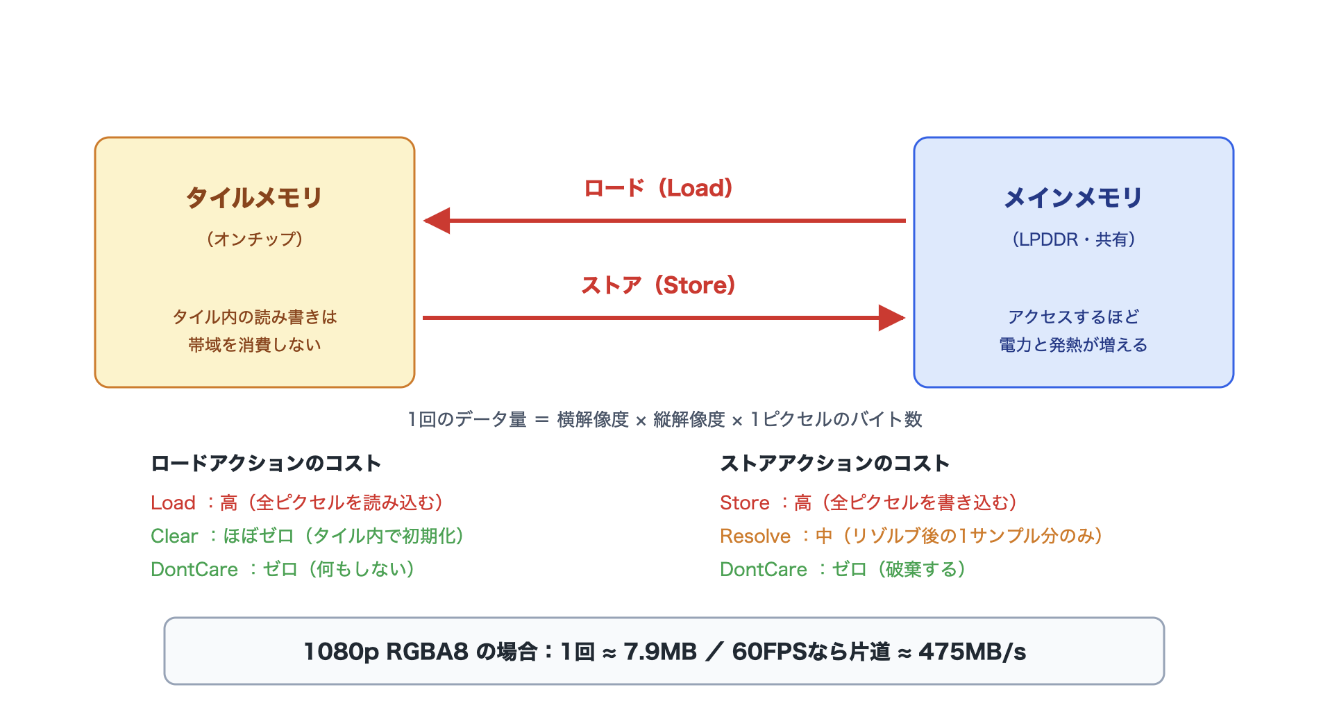
Figure 1.7: Tile memory ⇔ main memory load/store and bandwidth cost
1.2.3. Declaring Resource Usage with AccessFlags
So how are these load/store actions specified in Render Graph? In fact, Render Graph does not let you specify load/store actions directly. When adding a pass, you declare how resources are used to the builder, and Render Graph determines the actions from that information. What is used for this declaration is AccessFlags.
List 1.1: Declaring resources with AccessFlags
1 2 3 4 5 6 7 8 9 10 | public override void RecordRenderGraph(RenderGraph renderGraph, ContextContainer frameData) { using (var builder = renderGraph.AddRasterRenderPass<PassData>("Example", out var passData)) { // Declare the output attachment. // AccessFlags.WriteAll = this pass writes all pixels (the previous content is not needed) builder.SetRenderAttachment(_targetHandle, 0, AccessFlags.WriteAll); ... } } |
The main values of AccessFlags and their meanings are as follows.
| AccessFlags | Meaning | Effect on actions |
|---|---|---|
| Read | Reads the previous content | The load action becomes Load |
| Write | Writes (possibly only some pixels) | The previous content must be preserved, so the load may become Load |
| ReadWrite | Both reads and writes | The load becomes Load |
| Discard | The previous content may be discarded | The load can be DontCare |
| WriteAll | Writes all pixels (Write + Discard) | The load can be DontCare |
Pay particular attention to the difference between Write and WriteAll. A plain Write declares that "only some pixels may be written," so Render Graph has no choice but to set the load action to Load in order to preserve the contents of the pixels that were not written. For passes that always overwrite every pixel, such as a full-screen Blit, specify WriteAll. For 1080p RGBA8, this difference in specification alone determines whether a load of about 8 MB per frame occurs. On the other hand, the store action is determined by whether the resource is used in a subsequent pass. This is not specified by the developer; Render Graph decides it by looking at the entire graph. The next subsection looks at those rules.
1.2.4. Rules by Which Render Graph Determines Actions
When Render Graph builds Native Render Passes from the resource usage information of all recorded passes, it determines the load/store action of each attachment. The decision rules are summarized as follows.
Determining the Load Action
| Condition | Determined action |
|---|---|
| Declared with AccessFlags.WriteAll (or Discard) | DontCare |
| First use of the resource, and a clear is requested | Clear |
| The previous content is read or partially written | Load |
Determining the Store Action
| Condition | Determined action |
|---|---|
| Not used by any subsequent pass | DontCare |
| Used by a subsequent pass via UseTexture (as a texture) | Store |
| Used by subsequent passes only as SetInputAttachment (input attachment) and merged into the same Native Render Pass | DontCare (passed through tile memory) |
| Set as a global texture | Store (conservatively stored because subsequent use is not visible to Render Graph) |
| MSAA with a resolve target | Resolve |
Two practical guidelines follow from these rules.
- Make global textures a last resort. A texture made global with
SetGlobalTextureAfterPassor similar can no longer have its usage tracked by Render Graph, so it is always stored and is also excluded from memoryless conversion. Writing code that makes things global "just in case" prevents the optimization from taking effect. UseTextureandSetInputAttachmentare entirely different in terms of bandwidth. Even though both "read the result of the previous pass," the former incurs a store→sample round trip, while the latter can be completed within tile memory (covered in detail in the "Frame Buffer Fetch" section).
Handling Imported Textures
When a texture managed on the application side, such as RTHandle, is imported with renderGraph.ImportTexture, Render Graph does not know how that texture is used outside the graph. It is therefore treated conservatively by default (it is loaded even on first use and stored even after the last use). Passing ImportResourceParams at import time relaxes this conservative behavior.
List 1.2: Parameter settings at import
1 2 3 4 5 6 | var importParams = new ImportResourceParams { clearOnFirstUse = true, // Clear on first use (the load can be Clear) discardOnLastUse = true, // Discard after the last use (the store can be DontCare) }; var handle = renderGraph.ImportTexture(_rtHandle, importParams); |
If an imported texture is "recreated every frame, so the previous content is not needed," set clearOnFirstUse/discardOnLastUse. For textures managed by Render Graph (those created with renderGraph.CreateTexture), all of this is determined automatically. As a rule, leave everything except textures that truly require lifecycle management to Render Graph.
Reading Load/Store Actions
Now that we know the rules, let us read an actual frame. Looking at a standard URP forward rendering frame in Render Graph Viewer, you can observe a structure like the following, for example.
| Pass | Attachment | Load | Store |
|---|---|---|---|
| MainLightShadow | Shadow map (depth) | Clear | Store |
| DrawOpaqueObjects | Camera color | Clear | (depends on subsequent passes) |
| Camera depth | Clear | (depends on subsequent passes) | |
| DrawTransparentObjects | Camera color | (continues when merged) | Store |
| FinalBlit | Back buffer | DontCare | Store |
The key points for reading this are as follows.
- A shadow map is something that is "drawn and then sampled later," so it cannot be anything other than Store. This is a store that cannot be removed.
- If opaque and transparent passes are merged into a single Native Render Pass, no store/load of the camera color occurs between them. Conversely, if something is inserted between them and the merge breaks, a round trip appears there.
- Also pay attention to the store action of the camera depth. Turning on Depth Texture causes the camera depth to be stored. It is a common waste in real projects that the setting is on even though no shader or post-processing requires
_CameraDepthTexture.
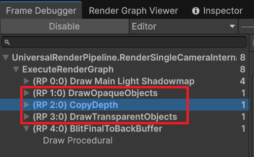
Figure 1.8: Copy Depth splits Draw Opaque Objects and Draw Transparent Objects
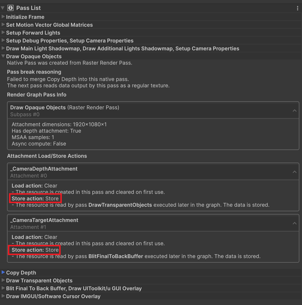
Figure 1.9: Because they are split, Store occurs at the end of Draw Opaque Objects
In this way, the basic flow of tile memory optimization is to check, one by one, whether each attachment's Store has a legitimate reason (subsequent use).
1.2.5. Reduction Example with AccessFlags
Finally, let us confirm with a concrete example that the actions change with the AccessFlags specification alone. For a pass that performs a full-screen Blit, we compare the case where the output attachment is declared with Write and the case where it is declared with WriteAll.
List 1.3: Comparison of AccessFlags Write and WriteAll
1 2 3 4 5 | // Pattern A: Write (does not declare writing all pixels) builder.SetRenderAttachment(_targetHandle, 0, AccessFlags.Write); // Pattern B: WriteAll (declares writing all pixels) builder.SetRenderAttachment(_targetHandle, 0, AccessFlags.WriteAll); |
The rendering result is the same in both cases. However, when checked in Render Graph Viewer, the load action is Load in pattern A and DontCare in pattern B. Because this is a full-screen Blit, the loaded content is entirely overwritten and thrown away. In other words, the load in pattern A is wasted.
1.3. Render Pass / Subpass
We have seen that store→load round trips between passes are a cost. This section explains Render Pass/Subpass, the mechanism for eliminating that cost, and pass merging by Render Graph.
1.3.1. Resource Dependencies and the DAG
The process of completing the image of a game in one frame is called the rendering pipeline, and each individual process that makes it up is called a rendering pass. Each pass has resource dependencies: which resources it reads and which resources it writes. For example, typical geometry rendering that includes deferred rendering has the following dependencies.
- Create the depth buffer with a depth pre-pass
- Draw opaque objects to the G-Buffer (using the depth buffer)
- Perform deferred lighting into the opaque buffer (using the G-Buffer and depth buffer)
- Draw transparent objects to the transparent buffer (using the depth buffer)
- Composite the opaque buffer and transparent buffer and draw to the frame buffer
If passes are drawn as nodes and resource dependencies as edges, this pipeline becomes a directed acyclic graph (DAG). Pass 4 does not use the outputs of passes 2 and 3, so it can run in parallel as long as the dependencies are communicated to the GPU.
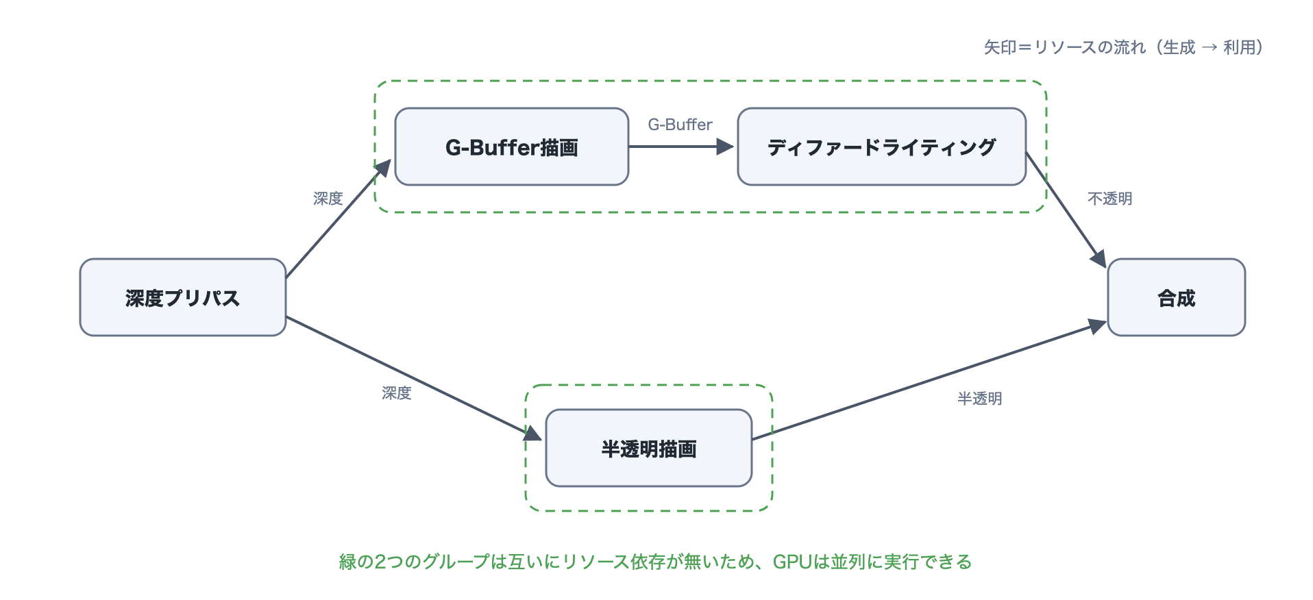
Figure 1.10: DAG of rendering passes and parallelization
The "Graph" in the name Render Graph refers to this DAG. Render Graph is a system that collects the resource dependencies of passes, builds a DAG, and creates an execution plan based on it.
1.3.2. Vulkan RenderPass/Subpass
As a mechanism for communicating resource dependencies to the GPU, Vulkan has the concepts of RenderPass and Subpass. What Render Graph ultimately builds is this Vulkan RenderPass, so we briefly discuss the API level. A Vulkan RenderPass consists of the following elements.
- Attachments: declarations of the render targets used in the RenderPass. For each attachment,
loadOp(load action) andstoreOp(store action) are specified. These are the actual form of the actions seen in the previous section, "Tile Memory Load/Store." - Subpasses: units of drawing within a RenderPass. Each subpass declares its output attachments (color/depth) and input attachments.
- Subpass dependencies: declarations of the execution order and memory dependencies between subpasses.
There are two properties to keep in mind here.
- Load/store occurs only at RenderPass boundaries, not between subpasses. In other words, if multiple processes can be configured as subpasses of a single RenderPass, the intermediate results between them stay in tile memory.
- Input attachments let you read the result of a previous subpass, but only at the same pixel position. This is the API-level form of the frame buffer fetch covered in the next section.
Expressing the geometry rendering above with RenderPass/Subpass gives the following.
- Geometry rendering (RenderPass)
- Depth pre-pass (Subpass) ― Output: depth
- G-Buffer rendering (Subpass) ― Input: depth / Output: G-Buffer
- Deferred lighting (Subpass) ― Input: G-Buffer / Output: opaque buffer
- Transparent rendering (Subpass) ― Input: depth / Output: transparent buffer
- Composite (Subpass) ― Input: opaque and transparent buffers / Output: frame buffer
With this configuration, depth, the G-Buffer, the opaque buffer, and the transparent buffer are all passed between subpasses, and only the final output frame buffer crosses the RenderPass boundary. A configuration that could have incurred five stores now incurs one. Incidentally, Metal has an equivalent mechanism. A Metal Render Pass has load/store actions and allows fragment functions to read color attachments in tile memory directly (as well as tile shaders). Metal has no explicit subpass declaration like Vulkan, but the optimizations performed by Render Graph work on Metal in the same way.
1.3.3. Unity's Native Render Pass
So how does Render Graph handle this Vulkan RenderPass/Subpass? The first thing to understand is that a pass added with AddRasterRenderPass does not become a subpass as is. A pass added with RecordRenderGraph is only a logical pass of Render Graph. After all passes in the frame have been recorded, Render Graph does the following in the compile step.
- Build the DAG from the resource dependencies and prune unnecessary passes (culling)
- Merge adjacent passes that satisfy the conditions into one Native Render Pass (equivalent to a Vulkan RenderPass), and make each merged pass a subpass
- Determine the load/store action of each attachment (see "Rules by Which Render Graph Determines Actions" in the previous section)
- Make eligible resources memoryless (the "Memoryless" section)
In other words, the developer's job is not to assemble subpasses by hand, but to design passes in a mergeable form and declare resource usage correctly. Whether merging succeeded is checked with the (RP n:m) notation in the Frame Debugger and with Render Graph Viewer.
1.3.4. Pass Merge Conditions
The conditions under which Render Graph merges passes are summarized below.
- Both are Raster Render Passes.
AddComputePassandAddUnsafePassare not merged. If a Compute pass is inserted in a sequence of Raster passes, the Native Render Pass is broken there. - The passes are recorded consecutively. Merging is performed between passes that are adjacent in the graph.
- The output attachment resolutions match. If the resolution of an intermediate buffer is changed (downsampled), merging is not possible at that boundary.
- The MSAA sample counts match.
- The later pass does not use the output of the earlier pass as a texture. Use via
UseTexturerequires store→sample and therefore prevents merging. Use asSetInputAttachment(input attachment) does not prevent merging. Input attachments and textures are different things. - The total number of attachments does not exceed the limit (8). There is an upper limit on the total number of attachments used by the merged Native Render Pass.
- There is no use that escapes Render Graph's tracking, such as making a texture global.
If even one condition is not met, that pass becomes a standalone Native Render Pass. The reason a pass was not merged is shown in Pass Break Reasoning in Render Graph Viewer, so check it first when passes are not merged.
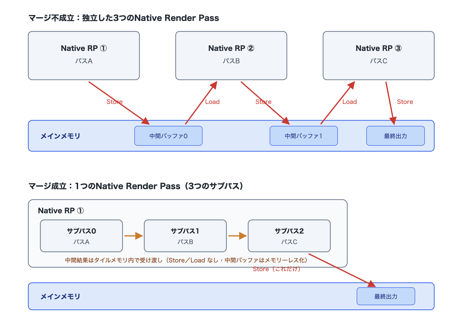
Figure 1.11: Comparison of Native Render Pass structure before and after merging
1.4. Frame Buffer Fetch
We have seen that passes can be merged into one Native Render Pass when the conditions are met. This section explains Frame Buffer Fetch (hereafter FBF), a technique for reading the result of a previous subpass directly from tile memory between merged subpasses.
1.4.1. What Is Frame Buffer Fetch
Consider deferred rendering, which creates a G-Buffer and performs lighting. A simple implementation proceeds as follows.
- Create the G-Buffer (write albedo, normals, and material information to tile memory)
- Store the albedo, normals, and material information to main memory
- Sample the stored G-Buffer as textures and perform deferred lighting
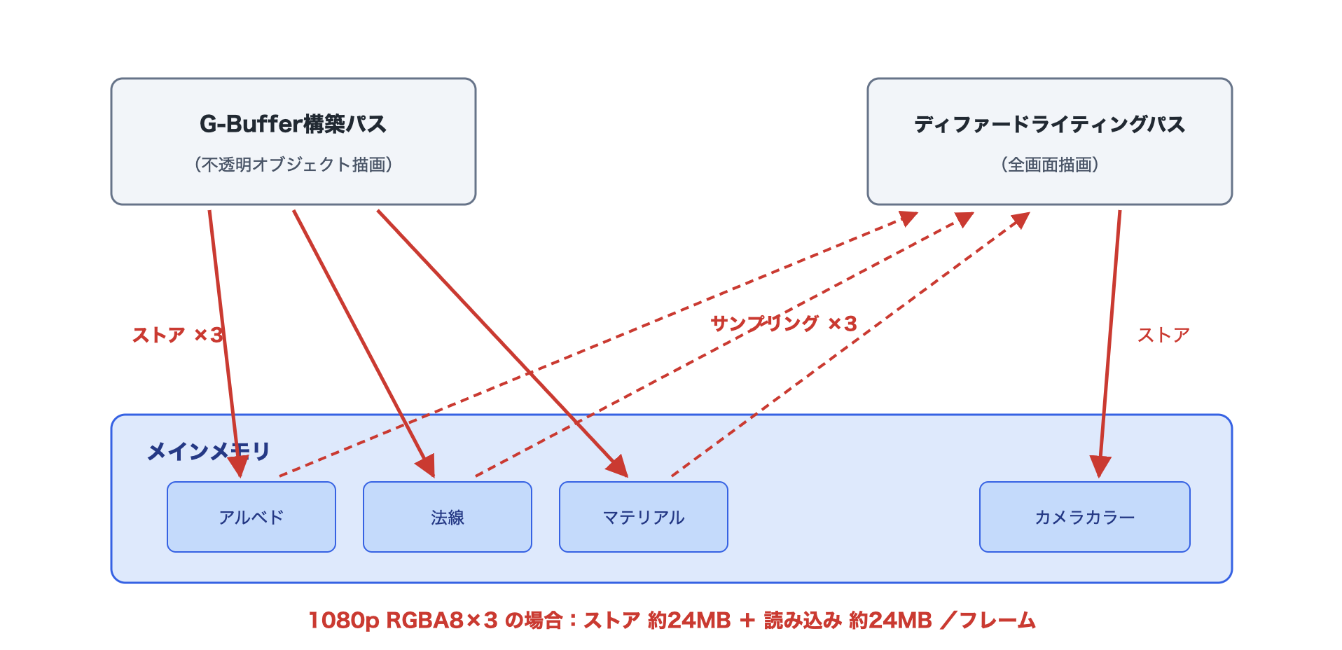
Figure 1.12: Data flow of simple deferred rendering
A question arises here. What the lighting pass wants to read is the G-Buffer value "of the pixel currently being processed." That value has just been written to the tile memory of the same tile by the preceding pass. Can it not be read directly from tile memory without a round trip to main memory? FBF makes this possible. With FBF, the processing becomes as follows.
- Create the G-Buffer (write to tile memory)
- Read the G-Buffer directly from tile memory and perform deferred lighting
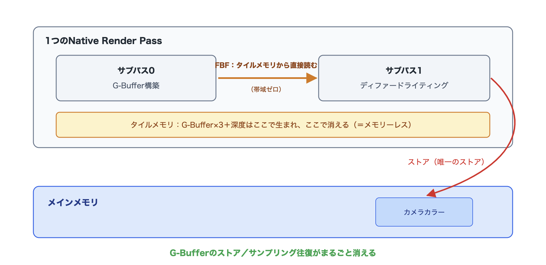
Figure 1.13: Data flow of deferred rendering using frame buffer fetch
The stores of the three G-Buffer targets and the reads for sampling them are eliminated. For three 1080p RGBA8 targets, this reduces bandwidth by about 24 MB per frame for the stores alone, or about 1.4 GB/s at 60 FPS. At the API level, FBF is realized as the Vulkan input attachment mentioned in the previous section, "Vulkan RenderPass/Subpass" (direct reading of the color attachment in Metal). FBF can therefore be used only between subpasses within the same Render Pass. Passes being merged is a prerequisite for FBF.
1.4.2. Understanding the Constraints
FBF is not a replacement for texture sampling. It has the following constraints.
- It can read only the same pixel position as the fragment being processed. Tile memory holds only the contents of "the tile currently being processed," so offset sampling (reading neighboring pixels) is impossible in principle.
- Filtering and mipmaps cannot be used. Only a single-value load is available.
- The input-side and output-side resolutions must match (this is also a merge condition).
Let us look at an example where constraint 1 applies. Consider the process of "applying UV-distorting noise processing to the result of monochrome/sepia compositing." The noise shader samples with shifted UVs as follows.
List 1.4: Noise processing shader
1 2 3 4 5 | // Distort the UVs using noise float2 distortedUV = input.texcoord + noise * 0.02; // Sample the texture with the distorted UVs. // Frame buffer fetch cannot be used because the load position differs from the fragment position. half4 color = SAMPLE_TEXTURE2D_X(_BlitTexture, sampler_LinearClamp, distortedUV); |
Because the position to read differs from the position of the fragment being processed, this pass cannot use FBF. The composite result must be declared with UseTexture, and a store→sample round trip occurs between the composite pass and the noise pass. For this reason, checking at the effect design stage whether "this pass reads only the same pixel" lets you judge early whether FBF can be used. Processes that need only the same pixel (tone mapping, color grading, compositing, deferred lighting) are FBF candidates, while processes that read neighboring pixels (blur, distortion, Bloom) use textures.
1.4.3. Inside the Shader API
To use FBF from a Unity shader, use the macros provided by SRP Core.
List 1.5: How to use frame buffer fetch
1 2 3 4 5 6 7 8 9 | // Declare input attachment 0 FRAMEBUFFER_INPUT_X_HALF(0); half4 frag(Varyings input) : SV_Target { // Load the value at the fragment position being processed from input attachment 0 half4 color = LOAD_FRAMEBUFFER_X_INPUT(0, input.positionCS.xy); ... } |
The macros have variations depending on precision and purpose.
| Declaration macro | Load macro | Purpose |
|---|---|---|
| FRAMEBUFFER_INPUT_HALF(n) | LOAD_FRAMEBUFFER_INPUT(n, pos) | half-precision color |
| FRAMEBUFFER_INPUT_FLOAT(n) | LOAD_FRAMEBUFFER_INPUT(n, pos) | float precision |
| FRAMEBUFFER_INPUT_X_HALF(n) | LOAD_FRAMEBUFFER_X_INPUT(n, pos) | XR (single-pass instancing) compatible version |
Variations with _X, like the TEXTURE2D_X macros, support XR render target arrays. In projects that may support XR, it is safe to standardize on the variants with _X. Knowing what these macros expand to on each platform makes it easier to understand the behavior and the fallback.
| Platform | Expands to | What it is |
|---|---|---|
| Vulkan | subpassInput + subpassLoad | Render Pass input attachment |
| Metal | Color attachment read via the [[color(n)]] attribute | Direct read of tile memory |
| OpenGL ES | Extensions such as GL_EXT_shader_framebuffer_fetch (supported GPUs only) | Falls back as below when the extension is unsupported |
| Unsupported environments | Regular texture (_UnityFBInput0, etc.) + load instruction | Not FBF; becomes a regular texture read |
Note the last row. The macros fall back so that they still work in unsupported environments, but in that case there is no bandwidth reduction. In other words, just because it works does not mean FBF is taking effect. To check whether it is effective, use the action display in Render Graph Viewer (whether the store of the input-side buffer is DontCare) and measurement of bandwidth on a physical device.
1.4.4. The Difference Between SetInputAttachment and UseTexture
On the C# side, declare the resource to be read with FBF using SetInputAttachment.
List 1.6: Declaring an input attachment
1 2 3 4 5 6 7 8 9 | using (var builder = renderGraph.AddRasterRenderPass<PassData>("Lighting", out var passData)) { builder.SetRenderAttachment(cameraColor, 0, AccessFlags.Write); // Corresponds to FRAMEBUFFER_INPUT_X_HALF(0) in the shader builder.SetInputAttachment(gBufferAlbedo, 0); // Corresponds to FRAMEBUFFER_INPUT_X_HALF(1) builder.SetInputAttachment(gBufferNormal, 1); ... } |
The index in the second argument of SetInputAttachment corresponds to the n of FRAMEBUFFER_INPUT_X_HALF(n) on the shader side. Here, the following table summarizes the differences from UseTexture, which has appeared repeatedly since the "Tile Memory Load/Store" section.
| Item | UseTexture | SetInputAttachment |
|---|---|---|
| Readable position | Any UV (offset, filtering, and mips allowed) | Only the fragment position being processed |
| Merging with the previous pass | Prevents | Does not prevent |
| Store of the previous pass's output | Store is forced | Can be DontCare when the merge holds |
| Bandwidth cost | Store + sampling read | Zero (completed within tile memory) |
| How to read in the shader | SAMPLE_TEXTURE2D family | LOAD_FRAMEBUFFER family |
1.4.5. Fetching Depth
Not only color but also depth resides in tile memory. If depth can be fetched, it may be possible to eliminate the _CameraDepthTexture store→sample round trip even for processes that "reference the scene depth," such as soft particles, decals, and fog. SRP Core provides a set of macros for handling depth input attachments, but turning a depth attachment into an input is an area where constraints depending on the platform and URP version tend to arise. Until verification results are available, this chapter recommends the following alternative, which is certain to work. As an alternative, you can write depth to a color attachment and fetch it. In the subpass that builds the G-Buffer, write the linearized depth value to one channel of a color attachment (such as R16_Float), and read it with FBF in subsequent subpasses. This adds one attachment, but if it is made memoryless, the real memory cost is zero, and the store round trip of the depth texture is reliably eliminated.
1.4.6. Platform Differences and Pitfalls
Finally, here are the platform differences to check when using FBF.
| Environment | FBF support | Notes |
|---|---|---|
| Vulkan (Adreno) | ○ Input attachment | Widely supported. Driver quality depends on the device |
| Vulkan (Mali) | ○ Input attachment | Widely supported |
| Vulkan (IMG / Pixel 10) | ○ Input attachment | TBDR. Watch for driver-specific behavior differences ("GPU Vendor Differences" in the final section) |
| Metal (Apple) | ○ Color attachment read | Works reliably |
| OpenGL ES | △ Depends on extension | Only GPUs that support GL_EXT_shader_framebuffer_fetch. Others fall back |
| Editor (D3D, etc.) | × Fallback behavior | Works as a regular texture. You can verify operation but cannot measure the effect |
The following three points deserve particular attention.
- The effect is not visible in the Editor. Because the fallback renders correctly, build your workflow on the assumption that the difference becomes apparent only when measured on a physical device.
- When MSAA is used together, the merge condition (matching sample counts) is more likely to be violated. Camera color with MSAA enabled and an intermediate buffer created without MSAA cannot be merged. Duplicate the TextureDesc of the intermediate buffer from the original Desc, as in
GetTextureDesc(cameraColor), so that the sample count is inherited. - There is a limit on the number of input attachments that one subpass can read. The limit of 8 attachments in total ("Pass Merge Conditions" in the previous section) includes the input side. When designing the G-Buffer, save attachments through channel packing.
1.5. Memoryless
So far, we have been able to eliminate both the load and the store of intermediate buffers. This raises a question. Does a buffer that is neither loaded nor stored need an entity in main memory?
1.5.1. What Is Memoryless
In fact, it does not. A resource that is used only in tile memory and discarded in tile memory does not need a main memory allocation at all. This state is called memoryless. Vulkan/Metal have a mode for creating a resource that "exists only in tile memory (on-chip memory) and has no backing store in main memory" (LAZILY_ALLOCATED memory in Vulkan, MTLStorageMode.memoryless in Metal). A resource specified as memoryless has the following properties.
- It does not consume main memory (the app's memory footprint decreases)
- Load cannot be specified as the load action and Store cannot be specified as the store action (because there is no entity to read or write)
In other words, memoryless is something that holds as a result of eliminating load/store in the previous sections. If load/store is gone, the resource can be made memoryless, and if it cannot be made memoryless, a load or store still remains somewhere.
1.5.2. Conditions
Using the terms so far, the conditions under which a resource can be made memoryless are as follows.
- The load action is Clear or DontCare (the previous content is not read from main memory. This is the WriteAll/Discard declaration seen in the "Declaring Resource Usage with AccessFlags" subsection, or a Clear on first use)
- The store action is DontCare (it is not used as a texture by subsequent passes and is not carried over to the next frame. See the "Rules by Which Render Graph Determines Actions" subsection)
- Its use is completed within one Native Render Pass (passing between subpasses, that is, input attachments/FBF, is allowed. See merging in the "Render Pass / Subpass" section and FBF in the "Frame Buffer Fetch" section)
As you can see, these three conditions are exactly what the previous sections have explained.
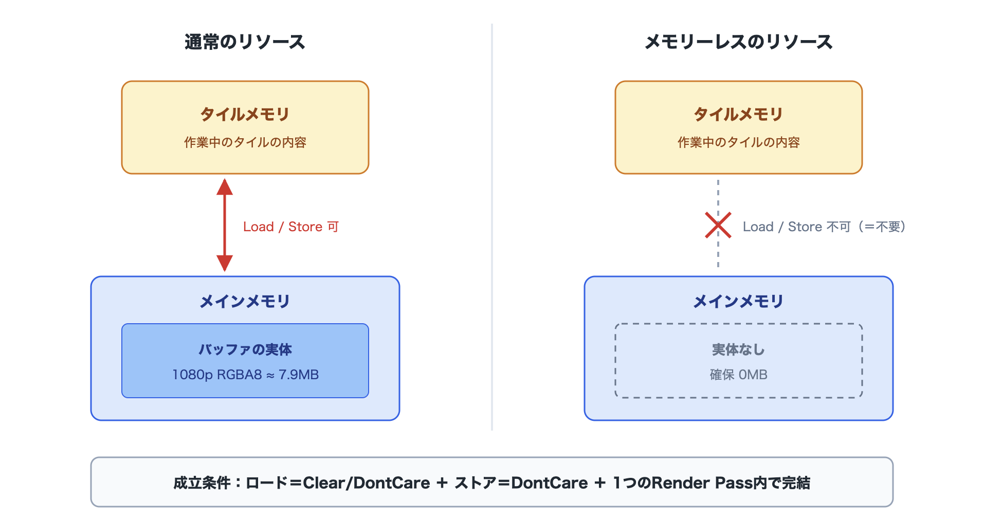
Figure 1.14: Memory map comparison before and after making resources memoryless
Automatic Memoryless Conversion and Explicit Specification
In Unity's Render Graph, memoryless is realized through two routes.
Automatic memoryless conversion
When a texture managed by Render Graph (created with renderGraph.CreateTexture) satisfies the three conditions in the "Conditions" subsection, Render Graph automatically makes it memoryless. The developer does not need to specify anything. Whether a resource has been made memoryless can be checked in the Resource List of Render Graph Viewer.
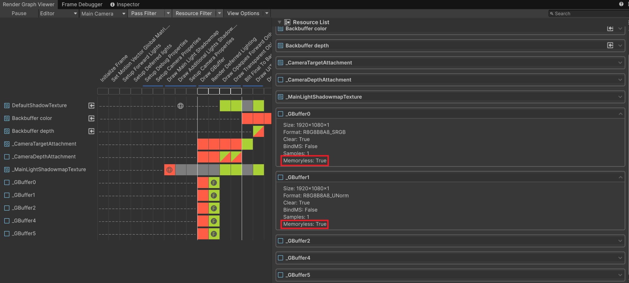
Figure 1.15: Memoryless display in Render Graph Viewer
Explicit specification
You can also specify it explicitly with the memoryless field of TextureDesc.
List 1.7: Explicitly specifying memoryless
1 2 3 4 | var desc = renderGraph.GetTextureDesc(universalResourceData.cameraColor); desc.memoryless = RenderTextureMemoryless.Color; // Specify memoryless desc.name = "Intermediate Texture"; var handle = renderGraph.CreateTexture(desc); |
Explicit specification has the advantage of leaving the design intent in the code. If you carelessly try to UseTexture a resource specified as memoryless in a subsequent pass, the inconsistency in the configuration surfaces at that point. If you leave it to the automatic mode, you cannot notice when a refactoring slips a UseTexture in somewhere and memoryless is lost (that is, memory usage and bandwidth increase). If the design intent is to keep a resource within tile memory, we recommend recording that in the code with an explicit specification.
1.5.3. Quantifying the Reduction
The reduction from memoryless can be calculated. The following are representative examples at 1080p.
| Resource configuration | Calculation | Reduction |
|---|---|---|
| One RGBA8 intermediate buffer | 1920×1080×4B | About 7.9 MB |
| One RGBA16F intermediate buffer | 1920×1080×8B | About 15.9 MB |
| Three G-Buffer targets (RGBA8) + depth | 7.9MB×4 | About 31.7 MB |
| 4x MSAA RGBA8 color | 1920×1080×4B×4 | About 31.7 MB |
| 4x MSAA depth (D32) | 1920×1080×4B×4 | About 31.7 MB |
As the table shows, MSAA and the G-Buffer yield the largest reductions. In particular, 4x MSAA color and depth together exceed 60 MB, so whether they are eliminated has a considerable effect on the memory budget of the whole app. Note that the reduction from memoryless is in "memory usage," while the reduction in bandwidth comes from the load/store reduction done in the previous sections. Keep in mind that these are separate metrics (memoryless holds as a result of load/store reduction, so in practice the two are achieved together).
1.5.4. Making MSAA Render Targets Memoryless
The effect of memoryless is greatest with MSAA. Let us start with the mechanism. With 4x MSAA, tile memory holds four samples of color and depth per pixel. However, what is finally displayed on screen is only the single sample obtained by averaging (resolving) the four samples. This is where the choice of store action matters.
- If you choose Store, the data for all four samples is written to main memory as is (four times the bandwidth, four times the memory).
- If you choose Resolve, the resolve is performed in tile memory, and only the single resolved sample is written out.
On a TBR GPU, the resolve can be performed in tile memory at almost no cost. And when Resolve is chosen, the four-sample MSAA buffer itself is not stored, so it satisfies the memoryless conditions. In other words, a correctly configured MSAA setup looks like this:
- MSAA color buffer (4 samples) → memoryless (no main memory allocation, no store)
- Resolve target buffer (1 sample) → regular store
- MSAA depth buffer (4 samples) → memoryless + no store (when depth is not used later)
This is why MSAA is said to be low-cost on TBR GPUs (compared with IMR). In URP, enabling the MSAA setting in the Universal Render Pipeline asset causes Render Graph to build this configuration automatically. What you should check is whether it has been broken. In Render Graph Viewer, check that the store action of the MSAA color buffer is Resolve and that Memoryless is yes. A typical case in which it breaks is when a subsequent pass requests the MSAA buffer itself as a texture (an incorrect declaration in a custom pass, a misconfigured Opaque Texture, and so on).
1.5.5. GPU Vendor Differences
The techniques covered in this chapter are all built on standard Vulkan/Metal features and work on the major vendors. Even so, understanding the characteristic differences between vendors makes it easier to interpret measurement results and troubleshoot.
| Vendor | Architectural characteristics | Notes |
|---|---|---|
| Qualcomm Adreno | GMEM-based binning. Depending on the rendering content, it may switch to direct mode (IMR-like behavior) | When it switches to direct mode, the effect of tile-memory-based optimizations changes. Check with a profiler which mode is in use |
| ARM Mali | TBR based on 16×16 tiles | Rich external bandwidth counters, making it the reference vendor for the bandwidth measurements in this chapter |
| Imagination (IMG) | TBDR with hardware hidden surface removal (HSR). The IMG DXT in Pixel 10 falls into this category | HSR inherently reduces opaque overdraw, so where optimization pays off differs from other vendors. Because the drivers are new, verifying behavior differences is recommended |
| Apple | TBDR in the PowerVR lineage. Tile memory can be handled explicitly in Metal | FBF/memoryless work reliably. It is also effective to confirm the effect on iOS before moving on to Android verification |
1.5.6. Conclusion
Let us summarize the four themes covered in this chapter once more. When using Render Graph, the developer does two things: declare resource usage correctly, and check the results with the Frame Debugger and Render Graph Viewer. This is unglamorous work, but its accumulation shows up as differences in device heat and battery consumption. We hope this chapter helps you optimize your projects.
1.5.7. References
- ARM, "Arm GPU Best Practices Developer Guide", https://developer.arm.com/documentation/101897/latest/
- Qualcomm, "Adreno GPU Best Practices", https://docs.qualcomm.com/doc/80-78185-2/topic/mobile_best_practices.html
- Apple, "Metal Best Practices Guide", https://developer.apple.com/library/archive/documentation/3DDrawing/Conceptual/MTLBestPracticesGuide/
- Unity, "Render graph system" (URP Documentation), https://docs.unity3d.com/Manual/urp/render-graph.html
- Rendering "Lighting and Reflections" to the Fullest on Mobile in Gakuen Idolmaster [CEDEC2024], https://gamemakers.jp/article/2025_01_29_90729/
- How to Achieve Blazing-Fast Deferred Rendering on Mobile, CEDiL, https://cedil.cesa.or.jp/cedil_sessions/view/2457
- Mastering RenderGraph from Unity 6: Basic Features, https://blog.sge-coretech.com/entry/2024/06/04/171757
- Mastering RenderGraph from Unity 6! Advanced Implementation 1: "Building a RenderPass", https://blog.sge-coretech.com/entry/2024/09/11/105032
- Introduction to Shader Optimization, Part 2: "What Is a Tile-Based Rendering GPU?", https://blog.sge-coretech.com/entry/2025/01/27/145242